Lei Feng network (search "Lei Feng network" public concern) by: The author of this article is Xiao Peng automotive engineers.
Electric vehicle power batteries require high power density, high energy density, long life, environmental protection and other requirements, and lithium batteries have the above advantages, so they are widely used in electric vehicles, and today say lithium batteries and manage their systems .

Lithium batteries for vehicles have the following:

For other types, the battery discharge temperature is -20~55°C. Charging temperature is 0~45°C. If Li4Ti5O12/LTO is used as anode material, the charging temperature can reach -30°C. Usually, the operating voltage range of lithium battery is 1.5V~4.2V (wherein C/NCA, C/NCM, C/LMO is 2.5V~4.2V; LTO/C/LMO is 1.5V~2.7V; C/LFP is 2.0V~3.7V).
Usually the temperature is 90 ~ 120 °C, SEI film began to enter the heat decomposition (Figure 1).
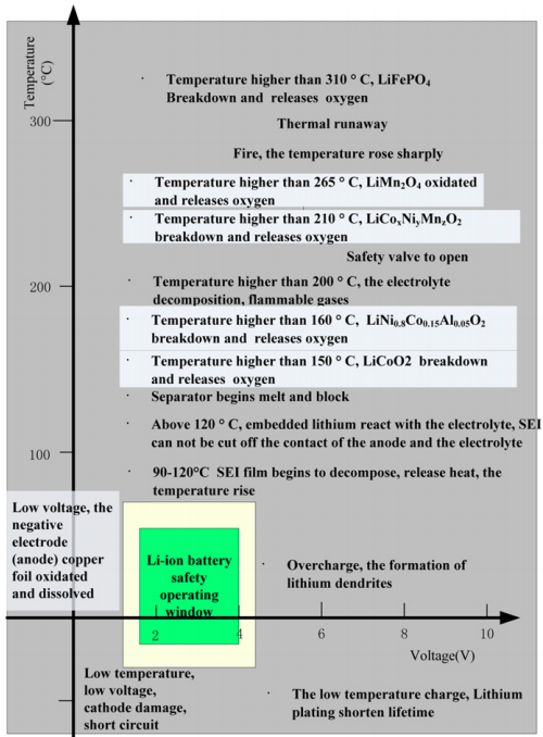
Figure 1 Battery Safety Work Area
Some electrolytes may even be decomposed at very low temperatures; when the temperature exceeds 120°C, the SEI membrane cannot protect the negative reaction of the carbon negative electrode with the organic electrolyte to generate gas; when the temperature exceeds 130°C, the separator begins to melt and cut off the battery reaction. When the temperature is higher, the cathode material begins to decompose:
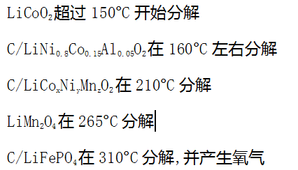
When the temperature exceeds 200°C, the electrolyte begins to decompose to produce a flammable gas.
Decomposed combustible gas and oxygen can undergo a violent chemical reaction and cause thermal runaway. A charging temperature of less than 0[deg.] C. results in the deposition of metallic lithium on the surface of the carbon negative electrode, thus reducing the cycle life of the battery. In the extreme case of low temperature, it will cause the negative electrode of the battery to puncture and cause short circuit. If the voltage is too low or the battery is over-discharged, the phase change causes the battery cell to collapse and affect the performance of the battery. It may even cause the negative current collector sheet to dissolve in the electrolyte. Excessive overdischarge also leads to reduced electrolytes and flammable gases and therefore potential safety risks. High voltage and overcharge can destroy the positive electrode composition and cause a large amount of heat generation. It also causes metal lithium to deposit on the surface of the negative electrode, which accelerates capacity decay and causes internal short circuit in the battery and causes safety problems. The electrolyte starts to decompose when the battery voltage is about 4.5V.
| Application in lithium batteries on electric vehiclesAt present, there are many types of power batteries used in electric vehicles. The widely used power batteries are generally made of LMO, LFP, NCM, and NCA as cathode materials, and carbon anode materials are used at the same time. At the same time, LTO has also been developed to improve battery life. And fast charge capacity.
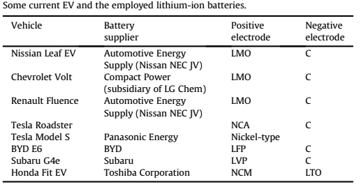
Table 1 Lithium Battery Applications for Electric Vehicles
BMS function and its key technology
| BMS functionCurrent commercial batteries must have BMS. The BMS can control and manage the battery more efficiently. Each battery operates within the range of operation, avoiding overcharging and overheating of the battery. The capacity of a single cell is relatively low, requiring a plurality of cells to be integrated into a module, and a battery system includes a plurality of modules. Usually a battery system contains hundreds or even thousands of cells. How to keep batteries operating in the proper range, BMS plays an important role.
The BMS function monitors the battery status, establishes the battery status, protects the battery, reports data, and balances. The main tasks of BMS in the vehicle are:
1. Protect the battery pack and battery pack from damage;
2. Make the battery work in a suitable voltage and temperature range;
3, after maintaining the battery in the appropriate conditions to run, to meet the needs of the vehicle.
Of course, BMS must also meet relevant standards and regulations. The basic hardware architecture of BMS is shown in Figure 2.
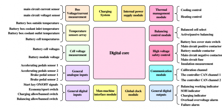
Figure 2 BMS basic hardware architecture
4, battery parameter detection: including total pressure, total current, single voltage detection, temperature detection, insulation detection, collision detection, impedance detection, smoke detection and so on.
5, battery state establishment: Including SOC, SOH, SOF.
6. Online diagnosis: Faults include sensor failures, network failures, battery failures, battery overcharge, and overdischarge. Overcurrent, insulation faults, etc.
7, battery safety protection and alarm: including temperature control system control and high pressure control, when diagnosed fault, BMS report the fault to the vehicle controller and charger, and cut off the high voltage to protect the battery from damage, including leakage protection.
8, charge control: BMS slow charge and fast charge control.
9. Battery Consistency Control: The BMS collects the voltage information of the cells, adopts a balanced method to make the batteries reach consistency, and the battery's balanced modes are dissipative and non-dissipative.
10, thermal management function: The collection temperature of each point of the battery pack, in charging and discharging over, BMS decide whether to open the heating and cooling.
11, network functions: including online calibration and health, online program download. The CAN network is usually used.
12. Information storage: BMS needs to store key data such as SOC, SOH, charge/discharge ampere hour, fault code and so on.
| BMS key technologyThe key technologies of BMS include accurate measurement of battery cell voltage, establishment of battery state, consistency of battery balance, and battery fault diagnosis technology.
1, single voltage measurement
Difficulties of single cell voltage measurement:
a. There are many batteries in the battery system that are connected in series and require multiple channels to collect the battery voltage. The voltage of each battery may be different, which brings difficulties to the design of the hardware circuit.
b. The measurement of the cell voltage requires a very high acquisition accuracy. In particular, the establishment of the SOC state of the cell requires a very high acquisition accuracy.
In the following, C/LPF and C/NCM are used as an example: Figure 3 shows the relationship between different open-circuit voltages and SOCs. From the figure, it can be seen that the OCV cancellation slope of C/NCM is relatively jittery, and the maximum per-mv voltage corresponds to the soc variation. The rate is 0.4% (except for 60~70%). If the measurement accuracy of the battery is 10mv, then the state error established by the SOC according to the OCV relationship will not exceed 4%. For C/NCM cells, the cell's measurement accuracy is within 10mv, but the OCV curve for C/LFP is relatively flat, and the voltage corresponding to the soc rate of change exceeds 4%, so the need for single cell voltage acquisition accuracy is high However, the accuracy of most acquisition chips can only reach about 5%. At present, the single-cell voltage acquisition mainly adopts the integrated chip method to collect, and some integrated chips are listed in Table 2.
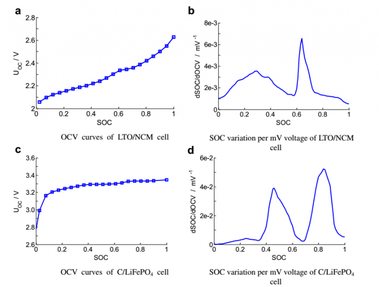
Fig. 3 Relationship between different open-circuit voltages and SOC and the impact on SOC per mv voltage (experimental temperature at 25°C, standing for 3h)

Table 2 different monomer voltage acquisition chip and its acquisition accuracy
2. Battery status establishment
Battery status includes SOC, SOF, SOH. The relationship between them is shown in Figure 4.
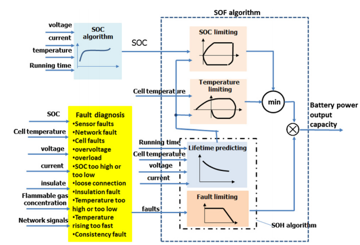
Figure 4 BMS state establishment algorithm framework
3, Soc algorithm:
1) Discharge test method;
2) Cumulative ampere hour method;
3) Open circuit voltage method, based on the relationship between OCV and SOC one-to-one correspondence, the accuracy is relatively high, but the battery needs to stand for a long time (at the same time need to consider voltage hysteresis, as shown in Figure 5);
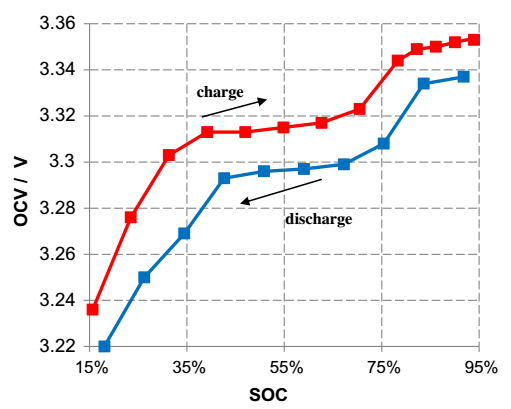
Fig. 5 OCV curves of lithium iron phosphate charge and discharge (measuring temperature 25°C, standing for 3h)
4. Battery Model Modeling: The open-circuit voltage method requires a long period of time to stand, and the battery model needs to be used to wait until the open-circuit voltage of the battery. The commonly used battery models include equivalent circuit models and electrochemical models. The equivalent circuit model can be expressed as follows:

among them,

If the battery model parameters are known, it is easy to obtain the open circuit voltage of the battery. According to the OCV-SOC curve table, the SOC status of the battery is obtained by query. Usually, the battery model adopts Rint model, first-order RC model and second-order model. The maximum error of the second-order model SOC is 4.3%, and the minimum error is 1.4%. The battery model method is used. Accuracy and model complexity are the key points to be considered. There are 12 effective circuit models, and the battery model can be used to dynamically establish the SOC. The accuracy of the SOC depends on the precision of the model and the accuracy of the signal acquisition. According to the related literature, the identification of the 12 equivalent circuit models and the comparison of the accuracy and complexity of the model show that the hysteresis of the first-order model is more suitable for the lithium iron phosphate battery. The model is simple and the precision is relatively high.
Electrochemical models are based on the transfer of matter and involve chemical thermodynamics and electrochemical theory. It is difficult to accurately express the parameters of many materials inside the battery, and it is often used in battery performance analysis and battery design.
5, neural network model: through the neural network model of the non-linear mapping characteristics, regardless of the battery's detailed information, and has universal applicability, suitable for the establishment of different battery SOC state. However, a large amount of training sample data and training data and training methods are required to greatly affect the accuracy of battery SOC. The neural network model requires a lot of data calculations and requires a high-performance CPU chip.
6, fuzzy algorithm: Need to have enough battery awareness and understanding, while the calculation is relatively large.
7. Perform SOC estimation based on other battery characteristics: Compare AC internal resistance and DC internal resistance (Figure 6).
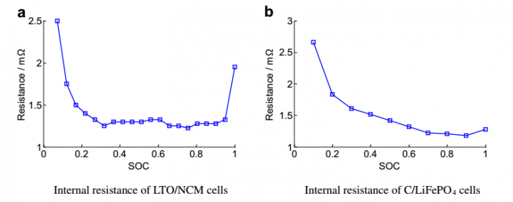
Figure 6 Relationship between battery DC resistance and SOC (measurement temperature 25°C, HPPC test method)
8, based on the above two or more integrated algorithms.
Current integration algorithms include simple corrections, weighted fusion algorithms, Kalman filtering (or extended Kalman filtering, EKF), sliding mode observers, and the like.
Simple correction integration algorithms mainly include:
1.) Ampere-hour integration algorithm and open-circuit voltage correction: The SOC is calibrated after the Amps integration algorithm is full.
For pure electric vehicles: a. The working conditions are simple. During the running of the vehicle, except for regenerative braking, it is mainly in the discharging state. When the vehicle is in the charging process, the battery is in the charging state, and the hysteresis of the open circuit voltage is easily established. b. The capacity of the battery pack is relatively large, and the AH integral is relatively small compared to the battery pack capacity. c. The probability of full charge is relatively large. The calibration of the initial SOC by the open circuit voltage can meet the accuracy requirements of pure electric vehicle SOC.
2.) Weighted Fusion Algorithm:
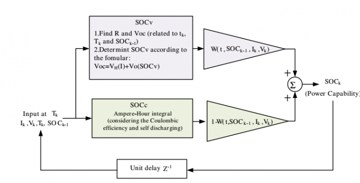
Figure 7 Weighted fusion algorithm
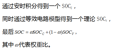
The current weighted fusion algorithm has been applied to the GM hybrid car.
The comparison of different SOC algorithms is shown in Table 3 and Table 4 below:
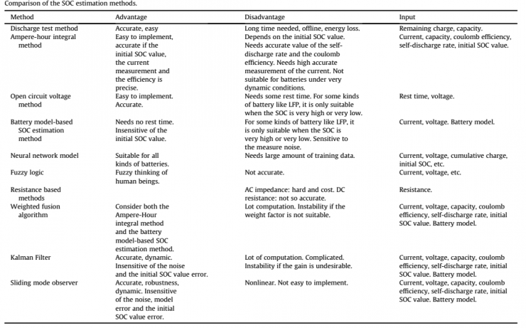
Table 3 Characteristics Comparison of SOC Algorithm
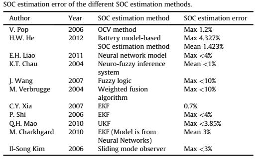
Table 4 Comparison of SOC algorithm accuracy
BMS manages and controls the power battery to work within the proper temperature and voltage range. It can be seen that BMS is important for electric vehicle cruising range, battery life, and battery safety.
Today, we briefly introduce the hardware architecture and software functions of the BMS, as well as several algorithms of the key point SOC, their related complexity, and the accuracy of the algorithm. In the follow-up, we will discuss further the changes in the OCV-SOC curve based on the voltage hysteresis of the NCA, NCM, and LFP, and the SOC algorithm basis. Welcome everyone to communicate.
Reference materials
1. Languang Lu, Xuebing Han, Jianqiu Li. A review on the key issues for lithium-ion battery management in electric vehicles. Journal of Power Sources, 2013 (226): 272-288.