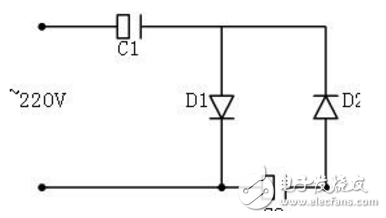
This simple electric cat uses a 220V AC power supply. The circuit is really simple. It consists of two rectifier diodes D1 and D2 and two capacitors C1 and C2. Its working principle is as follows:
During the positive half cycle (upper positive and negative), diode D1 is turned on, D2 is turned off, current is charged to C1 through D1, and the voltage on capacitor C1 is charged to near the peak and remains substantially unchanged. When the negative half cycle (upper negative and positive), the diode D2 is turned on and D1 is turned off. At this time, the voltage supply voltages on the Cl are added in series, and the current charges the capacitor C2 via D2. Repeatedly charged, the voltage on C2 is basically twice the power supply voltage. So it is called a double voltage rectifier circuit.
Take out the DC voltage of about 500V from both ends of C2 and add it to the special grid to receive our guests.
2. Prepare components:The above analysis shows that the voltage applied to the capacitor C1 is about 300V, the voltage applied to the capacitor C2 is about 500V, and the reverse voltage of the two rectifier diodes should be greater than 600V.
There are just a few broken energy-saving lamps on hand, open the lamp holder, take out the circular circuit board, and find that there are 5 diodes on the circuit board (1N4007, reverse voltage greater than 1000V), 2 electrolytic capacitors (3.3 microfarad, 250 Volt, this is the best. Immediately solder 2 diodes, 6 capacitors, measure it, no problem. The component is ready.

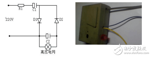
Due to the simple circuit and few components, it is decided to use the circuit board and solder directly to the plug wire. Use two capacitors in series for C1 to achieve a withstand voltage of 500V; use three capacitors in series for C2 to achieve a withstand voltage of 750V. Both D1 and D2 use 1N4007. After the welding is completed, the measured no-load voltage is as high as 580V.
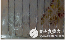
4. Making a mousetrap gridI found a plastic lid of the Guiyuan basket. I used two bare aluminum wires around it. The spacing was about 2 cm. When there was a cross, I put on the infusion hose and finally connected the two leads. I was done.

Direct connection to the 220V power supply is too dangerous. Considering the safety problem, a resistor (10K, 1W) is added in front, so the current is much smaller, but it is more than enough for the mouse. Also find a plastic box, put all the components in, add an indicator light.

Busy in the middle of the night, put it on the stove, put some pumpkin seeds that the mouse loves on the grid. When we went to bed the next morning, we saw our guests lying on the grid honestly.

There are many different versions of DIN Connectors. The name of each type comes from the number of pins the connector has (3-pin DIN, 4-pin DIN, etc.) Some of these pin numbers come in different configurations, with the pins arranged differently from one configuration to the next.
DIN cable connector 3-pin, 4-pin, 5-pin, 6-pin, 7-pin, 8-pin degree 180, 216, 240, 262, 270
DIN cables, DIN connector, telephone cable, computer cable, audio cable
ETOP WIREHARNESS LIMITED , https://www.wireharnessetop.com