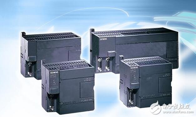
1. General expressions and features of function instructions
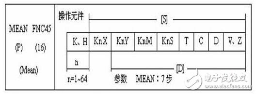
The expression of the function instruction is shown in the following table:
The function commands are organized by function number FNC00~FNC249. Each function instruction has an instruction mnemonic.
2, data length
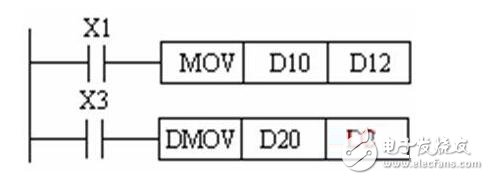
Function instructions can process 16-bit data and 32-bit data.
The first instruction in the following figure is to send the data in D10 to D12, which is processing 16-bit data. The second instruction is to send the data in D21 and D20 to D23 and D22, and process the 32-bit data.
3, function instruction type

The function commands of the FX series PLC are available in continuous execution mode and pulse execution type.
The program in the left is an example of a continuous execution mode. The above instruction is repeatedly executed every scan cycle when X2 is in the ON state. The program on the right is the pulse execution mode, which is valid only when X1 turns from OFF to ON.
4, bit components
Bit components: Components that only handle the ON/OFF state are called bit components.
Word component: a component that processes data is called a word component.
Combination of bit elements: Data processing can be performed by bit elements or word elements, and bit element combinations are represented by Kn plus head element numbers. The four bit elements are grouped into a unit, and n in KnM0 is the number of groups.
5, the index register V, Z
The index register is used to modify the component number of the operation object in the transfer and compare instructions. It operates in the same way as a normal data register. The (.) in [D.] indicates that the index register can be added. For 32-bit instructions, V is 16 bits high and Z is 16 bits low. When the index register is used in a 32-bit instruction, only Z is specified, and Z represents V and Z.
Second, the program flow control function instruction
Conditional jump instruction CJ
Subroutine call instruction CALL and return instruction SRET
Interrupt return instruction IRET, enable interrupt instruction EI and disable interrupt instruction DI
Main program end instruction FEND
Watchdog timer refresh instruction WDT
Loop start instruction FOR and loop end instruction NEXT
1, conditional jump instruction CJ
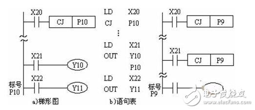
The CJ and CJP instructions are used to skip a part of the sequence program to reduce the scan time. Conditional jump instruction CJ application description
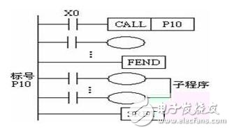
2, subroutine call instruction CALL and return instruction SRET
The subroutine should be written after the main program, ie the label of the subroutine should be written after the instruction FEND, and the subroutine must end with the SRET instruction.
3. Interrupt return instruction IRET, enable interrupt instruction EI and disable interrupt instruction DI
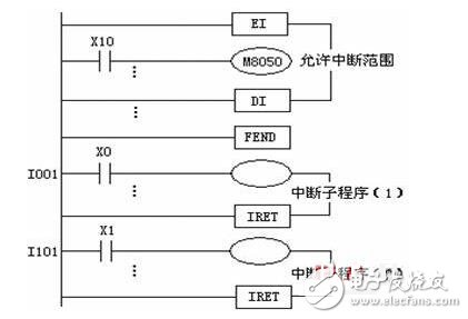
The PLC is generally in an interrupt-free state. The block between the commands EI~DI is the allowable interrupt interval, and the interrupt interval is between DI and EI. When the program executes to the allowable interrupt interval and an interrupt request signal occurs, the PLC stops executing the main program, executes the corresponding interrupt subroutine, and returns to the breakpoint to continue executing the main program when the interrupt return instruction IRET is encountered.
4, the main program end instruction FEND
The FEND instruction indicates the end of the main program and the start of the subroutine. When the program is executed to the FEND instruction, output processing, input processing, and watchdog timer refresh are performed. When it is completed, it returns to step 0.
The FEND instruction is typically used with the CJ-P-FEND, CALL-P-SRET, and I-IRET structures (P for the program pointer and I for the interrupt pointer). The pointers and subroutines, interrupt pointers, and interrupt subroutines of the CALL instruction should be placed after the FEND instruction. The subroutine called by the CALL instruction must end with the subroutine return instruction SRET. The interrupt subroutine must end with the interrupt return instruction IRET.
5, watchdog timer refresh command WDT
If the scan time (from step 0 to END or FEND) exceeds 100ms, Mitsubishi PLC will stop running. In this case, the watchdog timer should be refreshed by inserting the WDT instruction into the appropriate program step (scan time not exceeding 100ms).
6, loop start instruction FOR and loop end instruction NEXT
The program between FOR~NEXT is executed n times (specified by the operand) and then executed after the NEXT instruction. The number of cycles n ranges from 1 to 32767. If the value of n ranges from -32767 to 0, the number of loops is processed as 1.
FOR and NEXT always appear in pairs, and should be FOR before and NEXT after. The FOR~NEXT loop instruction can be nested up to 5 levels.
The FOR~NEXT loop body can be jumped out using the CJ instruction.
Antenk dip plug connector Insulation Displacement termination connectors are designed to quickly and effectively terminate Flat Cable in a wide variety of applications. The IDC termination style has migrated and been implemented into a wide range of connector styles because of its reliability and ease of use. Click on the appropriate sub section below depending on connector or application of choice.the pitch range from 1.27mm,2.0mm, and 2.54mm here.
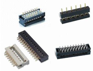
IDC DIP Plug Connectors Key Specifications/Special Features:
Materials:
Insulator: PBT, glass reinforced, rated UL94V-0
Contact: phosphor bronze or brass
Electrical specifications:
Pitch: 1.27/2.0/2.54mm
Current rating: 1A, 250V AC
Contact resistance: 30M Ohms (maximum)
Insulation resistance: 3,000M Ohms, minute
Dielectric withstanding voltage: 500V AC for one minute
Operating temperature: -40 to +105 degrees Celsius
Terminated with 1.27mm pitch flat ribbon cable
Number of contacts: 06,08, 10, 12, 14, 16, 20, 24, 26, 30, 32,34, 40, 50, 60 and 64P
With RoHS mark
Used for ribbon cables
DIP Plug Connectors Application
Wire to Board
Apply to Industries : PC, IPC, Consumer Electronics, Automotive, Home Appliance, Medical
Dip Connector,Dip Plug Connectors,Dip Direct Pulg Connector,IDC Plug Connector,Idc connector dip plug,1.27mm Dip Plug Connector,2.0mm Dip Plug Connector, and 2.54mm Dip Plug Connector
ShenZhen Antenk Electronics Co,Ltd , https://www.antenk.com