Direct current machine (direct current machine) refers to a rotating electric machine that can convert direct current electrical energy into mechanical energy (direct current motor) or convert mechanical energy into direct current electrical energy (direct current generator). It is a motor that can convert between DC electrical energy and mechanical energy. When it operates as a motor, it is a DC motor, which converts electrical energy into mechanical energy; when it operates as a generator, it is a DC generator, which converts mechanical energy into electrical energy.
A DC motor is composed of a stator and a rotor, with a certain air gap between them. The main feature of its structure is that it has an armature with a commutator. The stator of a DC motor is composed of a base, a main magnetic pole, a commutation magnetic pole, a front and rear end cover, and a brush holder. Among them, the main magnetic pole is the main component that generates the air gap magnetic field of the DC motor, and is composed of a permanent magnet or a laminated core with a DC excitation winding. The rotor of a DC motor is composed of an armature, a commutator (also called a commutator), and a shaft. The armature is composed of two parts: an armature core and an armature winding. The armature core is made of laminated silicon steel sheets, with cogging slots evenly distributed on its outer circle, and the armature windings are embedded in these slots. The commutator is a mechanical commutating component. After the commutating pieces are stacked into a cylindrical shape, they are formed into a whole with metal clips or plastic. The commutating segments are insulated from each other. The quality of the commutator has a great influence on the operational reliability.
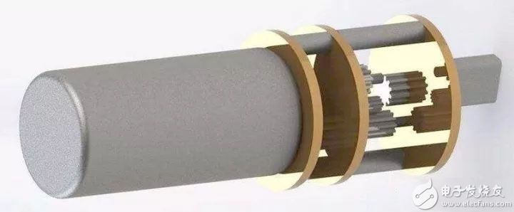
The basic structure of the DC motor and the design diagram of the DC motor drive circuit
Basic structure of DC motor
A DC motor is composed of a stator and a rotor, with a certain air gap between them.
The stator of a DC motor is composed of a base, a main magnetic pole, a commutation magnetic pole, a front and rear end cover, and a brush holder. Among them, the main magnetic pole is the main component that generates the air gap magnetic field of the DC motor, and is composed of a permanent magnet or a laminated core with a DC excitation winding.
The rotor of a DC motor is composed of an armature, a commutator (also called a commutator), and a shaft. The armature is composed of two parts: an armature core and an armature winding. The armature core is made of laminated silicon steel sheets, with cogging slots evenly distributed on its outer circle, and the armature windings are embedded in these slots.
The commutator is a mechanical commutating component. After the commutator pieces are stacked into a cylindrical shape, they are formed into a whole with metal clips or plastic. The commutating segments are insulated from each other. The quality of the commutator has a great influence on the operational reliability.
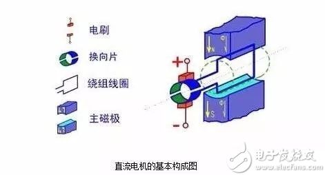
The basic structure of the DC motor and the design diagram of the DC motor drive circuit
The structure of the DC motor
The structure of a DC motor should be composed of two parts: the stator and the rotor. The static part of the DC motor is called the stator. The main function of the stator is to generate a magnetic field. It is composed of a frame, a main magnetic pole, a commutation pole, an end cover, a bearing, and a brush device. The part that rotates during operation is called the rotor. Its main function is to generate electromagnetic torque and induced electromotive force. It is the hub of the DC motor for energy conversion, so it is usually called the armature. It consists of the shaft, armature core, armature winding, and Composed of a fan and a fan.
stator
(1) Main magnetic pole
The role of the main pole is to generate an air gap magnetic field. The main magnetic pole is composed of two parts: the main magnetic pole core and the excitation winding. The core is generally made of 0.5mm~1.5mm thick silicon steel plate punched and riveted. It is divided into two parts, the pole body and the pole shoe. The part on which the excitation winding is covered is called It is the pole body, and the widened part below is called the pole shoe. The pole shoe is wider than the pole body, which can adjust the distribution of the magnetic field in the air gap and facilitate the fixation of the excitation winding. The field winding is made of insulated copper wire and sleeved on the core of the main magnetic pole. The entire main magnetic pole is fixed on the base with screws,
(2) Reversing pole
The function of the commutation pole is to improve the commutation and reduce the possible commutation spark between the brush and the commutator when the motor is running. It is generally installed between two adjacent main magnetic poles, consisting of the commutation pole core and the commutation pole. Polar winding composition. The commutating pole winding is made of insulated wire and sheathed on the commutating pole core, the number of commutating poles is equal to the main magnetic pole.
(3) Base
The housing of the motor stator is called the base. There are two functions of the base:
One is to fix the main magnetic pole, commutation pole and end cover, and to support and fix the entire motor;
The second is that the base itself is also a part of the magnetic circuit, so as to form a magnetic path between the magnetic poles, the part through which the magnetic flux passes is called a yoke. In order to ensure that the machine base has sufficient mechanical strength and good magnetic permeability, it is generally made of cast steel or welded by steel plates.
(4) Electric brush device
The brush device is used to introduce or draw DC voltage and DC current. The brush device is composed of a brush, a brush holder, a brush rod and a brush rod seat. The brush is placed in the brush holder and compressed with a spring to make a good sliding contact between the brush and the commutator. The brush holder is fixed on the brush rod, and the brush rod is mounted on the circular brush rod seat. Must be insulated between. The brush rod seat is installed on the end cover or the inner cover of the bearing, and the circumferential position can be adjusted and fixed after adjustment.
Rotor
(1) Armature core
The armature core is the main part of the main magnetic circuit and is used to embed the discharge armature winding. Generally, the armature core is laminated with punched sheets made of 0.5mm thick silicon steel sheets to reduce the eddy current loss and hysteresis loss generated in the armature core when the motor is running. The laminated core is fixed on the rotating shaft or the rotor support. An armature slot is opened on the outer circle of the iron core, and a discharge armature winding is embedded in the slot.
(2) Armature winding
The function of the armature winding is to generate electromagnetic torque and induced electromotive force. It is the key component of the DC motor for energy conversion, so it is called the armature. It is made up of many coils (hereinafter referred to as components) connected according to a certain rule. The coils are made of high-strength enameled wire or glass-fiber-coated rectangular copper wire. The coil sides of different coils are embedded in the armature slot in two layers. The coil and The cores and the upper and lower coil sides must be properly insulated. To prevent the centrifugal force from throwing the coil edge out of the slot, the slot is fixed with a slot wedge. The terminal part of the coil protruding out of the slot is bound with a thermosetting non-lattice glass tape.
(3) Commutator
In the DC motor, the commutator is equipped with brushes, which can convert the external DC power supply into the alternating current in the armature coil, so that the direction of the electromagnetic torque is constant; in the DC generator, the commutator is equipped with The brush can convert the alternating electromotive force induced in the armature coil into the direct current electromotive force drawn from the positive and negative brushes. The commutator is a cylinder composed of many commutating segments, and the commutating segments are insulated by mica sheets.
(4) Rotating shaft
The rotating shaft serves as a support for the rotation of the rotor, and requires a certain degree of mechanical strength and rigidity, and is generally made of round steel.
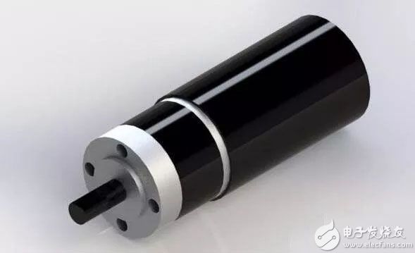
1. Design goal of DC motor drive circuit
In the design of the DC motor drive circuit, the following points are mainly considered:
1. Function: Does the motor rotate in one direction or in both directions? Does it require speed regulation? For a one-way motor drive, just use a high-power transistor or field effect tube or relay to directly drive the motor. When the motor needs to rotate in both directions, You can use an H-bridge circuit composed of 4 power components or use a double-pole double-throw relay. If you do not need to adjust the speed, just use a relay; but if you need to adjust the speed, you can use switching elements such as transistors, field effect tubes to achieve PWM (pulse width modulation) speed adjustment.
2. Performance: For the motor drive circuit of PWM speed regulation, there are mainly the following performance indicators.
1) Output current and voltage range, which determine how much power the circuit can drive.
2) Efficiency. High efficiency not only means saving power, but also reducing the heating of the drive circuit. To improve the efficiency of the circuit, you can start with ensuring the switching state of the power devices and preventing common-state conduction (a problem that may occur in an H-bridge or push-pull circuit, that is, two power devices are turned on at the same time to short-circuit the power supply).
3) Impact on the control input. The power circuit should have good signal isolation at its input terminal to prevent high voltage and large current from entering the main control circuit. This can be isolated by using a high input impedance or a photocoupler.
4) Impact on power supply. Common state conduction can cause an instantaneous drop in the power supply voltage and cause high-frequency power supply pollution; a large current may cause the ground potential to float.
5) Reliability. The motor drive circuit should be done as much as possible, no matter what kind of control signal is added, what kind of passive load, the circuit is safe.
2. Triode-resistor for gate drive
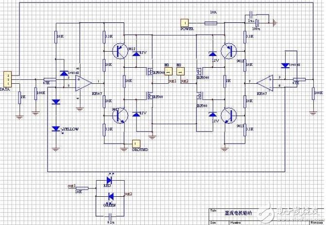
1. Input and level conversion part:
The input signal line is introduced by DATA, pin 1 is the ground line, and the rest are signal lines. Note that pin 1 is connected to the ground with a 2K ohm resistor. When the driver board and the microcontroller are powered separately, this resistor can provide a return path for the signal current. When the driver board and the single-chip microcomputer share a group of power supplies, this resistor can prevent large currents from flowing along the line into the ground wire of the single-chip microcomputer main board and causing interference. In other words, it is equivalent to separating the ground wire of the driver board from the ground wire of the single-chip microcomputer to achieve "one point grounding".
The function of the high-speed operational amplifier KF347 (TL084 can also be used) is a comparator, which compares the input logic signal with the 2.7V reference voltage from the indicator light and a diode, and converts it into a square wave signal close to the amplitude of the power supply voltage. The input voltage range of KF347 cannot be close to the negative power supply voltage, otherwise an error will occur. Therefore, a diode is added to the input terminal of the op amp to prevent the voltage range from overflowing. One of the two resistors at the input is used to limit the current, and the other is used to pull the input to a low level when the input is floating.
It is not possible to use LM339 or any other open-circuit output comparator to replace the op amp, because the high-level output impedance of the open-circuit output is more than 1 kiloohm and the voltage drop is large, and the transistor of the latter stage will not be cut off.
2. Gate drive part:
The circuit composed of transistors, resistors and voltage regulators further amplifies the signal, drives the gate of the FET and uses the gate capacitance of the FET itself (about 1000pF) for delay to prevent the FETs of the upper and lower arms of the H bridge. Simultaneous conduction ("common state conduction") causes a short circuit of the power supply.
When the output terminal of the op amp is low level (about 1V to 2V, it cannot reach zero completely), the lower triode is cut off, and the field effect tube is turned on. The upper transistor is turned on, the field effect tube is turned off, and the output is high. When the output terminal of the op amp is at a high level (about VCC-(1V to 2V), which cannot fully reach VCC), the lower transistor is turned on and the field effect tube is turned off. The upper transistor is cut off, the field effect tube is turned on, and the output is low level.
The above analysis is static, and the dynamic process of switching is discussed below: the on-resistance of the transistor is much less than 2 kiloohms, so when the transistor is switched from off to on, the charge on the gate capacitance of the FET can be quickly released. Cut off quickly. However, when the transistor is switched from on to off, it takes a certain amount of time to charge the gate of the field effect transistor through a 2 kiloohm resistor. Correspondingly, the speed at which the field effect tube switches from on to off is faster than from off to on. If the switching actions of the two transistors occur at the same time, this circuit can make the FETs of the upper and lower arms turn off first and then turn on, eliminating the common-state conduction phenomenon.
In fact, it takes a certain period of time for the output voltage of the op amp to change. During this time, the output voltage of the op amp is at the middle value between the positive and negative power supply voltages. At this time, the two transistors are turned on at the same time, and the field effect tube is turned off at the same time. So the actual circuit is safer than this ideal situation.
The 12V Zener diode of the FET grid is used to prevent the FET grid from overvoltage breakdown. The withstand voltage of the gate of the general field effect tube is 18V or 20V, directly adding 24V voltage will break down, so this Zener diode cannot be replaced by an ordinary diode, but it can be replaced by a 2 kiloohm resistor, and the same can be obtained. Partial voltage of 12V.
3. Field effect tube output part:
Inside the high-power FET, there are diodes in reverse parallel between the source and drain. When used as an H-bridge, it is equivalent to having four diodes connected in parallel at the output to eliminate voltage spikes, so there is no external diode. A small capacitor in parallel at the output (between out1 and out2) has certain benefits to reduce the peak voltage generated by the motor, but it has the side effect of generating peak current when using PWM, so the capacity should not be too large. This capacitor can be omitted when using a low-power motor. If you add this capacitor, you must use a high withstand voltage. Ordinary ceramic capacitors may experience breakdown and short-circuit faults.
A circuit composed of resistors, light-emitting diodes, and capacitors connected in parallel at the output indicates the direction of rotation of the motor.
4. Performance indicators:
The power supply voltage is 15~30 V, the maximum continuous output current is 5A/each motor, it can reach 10A in a short time (10 seconds), and the PWM frequency can be used up to 30KHz (usually 1 to 10KHz). The circuit board contains 4 logically independent power amplifier units whose output ends are connected in pairs to form an H-bridge, which can be directly controlled by a single-chip microcomputer. Realize the two-way rotation and speed regulation of the motor.
5. Wiring:
High-current lines should be as short and thick as possible, and try to avoid passing through vias. If you must pass vias, make the vias larger (>1mm) and make a circle of small vias on the pads. Use them when soldering. The solder fills up, otherwise it may burn. In addition, if a zener tube is used, the wire from the source of the FET to the power supply and ground should be as short and thick as possible, otherwise the voltage drop on this section of wire may pass through the forward-biased zener tube and The conducting transistor burns it. In the initial design, a 0.15 ohm resistor was used to detect the current between the source of the NMOS tube and the ground. This resistor became the culprit for the continuous burning of the board. Of course, this problem won't exist if the voltage regulator tube is replaced with a resistor.
3. Simple gate drive of low voltage drive circuit
Generally, the highest gate-source voltage of a power FET is about 20V, so in 24V applications, it is necessary to ensure that the gate-source voltage cannot exceed 20V, which increases the complexity of the circuit. But in 12V or lower voltage applications, the circuit can be greatly simplified.
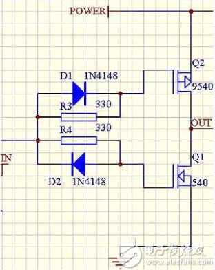
The picture above is one side of a 12V drive bridge. The transistor part of the above circuit is replaced by two diodes and two resistors. (Note that the logic in the above figure is reversed.) Due to the existence of the gate capacitance of the FET, the gate capacitance is charged through R3 and R4 to delay the conduction of the FET; and the gate capacitance is directly discharged through the diode to make the field effect The tube is cut off immediately, thereby avoiding common-state conduction.
This circuit requires that the input of the IN terminal is a steep-edge square wave pulse, so after the control signal is connected from the microcontroller or other open-circuit output equipment, it must pass through a Schmitt trigger (such as 555) or a high-speed comparator with push-pull output It can be connected to the IN terminal. If the input edge is too slow, the diode delay circuit will be useless.
The selection of R3 and R4 is related to the rising and falling speed of the IN signal edge. The steeper the signal edge, the smaller R3 and R4 can be selected, and the faster the switching speed can be. In the boost circuit used in Robocon competition (the principle is similar), 555 is used before IN.
Fourth, the edge delay drive circuit
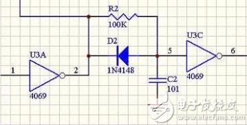
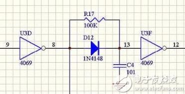
In the front-level logic circuit, the falling edge of the control PMOS and the rising edge of the NMOS are deliberately delayed, and then the square wave is formed, which can also avoid the common-state conduction of the field effect transistor. In addition, doing so can simplify the gate drive circuit of the subsequent stage, which can be a low-resistance push-pull drive gate, without considering the gate capacitance, and can better adapt to different field effect transistors. The following figure shows the delay circuit of two kinds of edges:
The following figure is the corresponding NMOS, PMOS gate drive circuit:
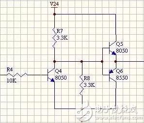
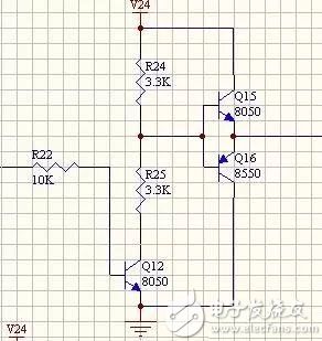
This gate drive circuit is composed of two-stage transistors: the front stage provides the correct voltage required to drive the gate of the FET, and the latter stage is a first-stage emitter follower, which reduces the output impedance and eliminates the influence of the gate capacitance. In order to ensure non-common state conduction, the input edge must be relatively steep, and the above-mentioned delay and then reshaping circuit can be done.
Five, several other drive circuits
1. The idea of ​​relay + semiconductor power device
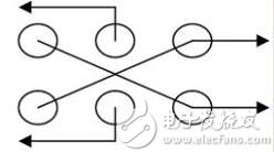
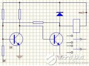
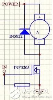
The relay has the advantages of large current and stable operation, which can greatly simplify the design of the drive circuit. In the motor drive circuit that needs to realize speed regulation, the relay can also be fully utilized. One solution is to use a relay to control the direction of the current to change the direction of the motor, and use a single super-high current FET (such as IRF3205, which generally only has an N-type super-high current tube) to achieve PWM speed regulation, as shown in the right figure below. This is a way to achieve a particularly high current drive. The commutation relay should be of double pole double throw type, the wiring is as shown in the left figure, and the coil wiring is as shown in the middle figure:
2. Several driver chips
1) L298
2) A3952
3) A3940
4) L6203
Six, the realization of PWM speed regulation
1. Algorithms using timers
//butcher add it
//The principle of the algorithm
//Programming implementation points
//Pros and cons
2. Algorithm using cyclic shift
The generation of the PWM signal can be done by a timer, but because 51 only provides two timers, if you want to output signals with different duty cycles to three or more DC motors, you need to set the timer repeatedly, which is more complicated. , We adopt a relatively simple method not only to provide different duty cycle input signals to more DC motors, but also to occupy only one timer resource. This method can be simply stated as follows:
Store the duty cycle information of the input signal required by each DC motor in a certain space of the memory. If the duty cycle is 1, save 0FFH (11111111B); if the duty cycle is 0.5, save 0F0H (11110000B) or any binary system The number includes four zeros and four ones. That is, the number of duty cycle = 1/8
The specific choice of binary number depends on the requirements of the output frequency. To output a PWM signal to this DC motor, as long as each time slice is shifted once, one fixed bit (which can be realized by bit addressing or carry flag C) is sent to the motor port. In addition, the shifting algorithm is an algorithm that relies on the previous results, so it is best to check or reset the shifted number regularly to prevent the shifting error from causing the error to continue.
The advantage of this algorithm is that it is an independent process and can realize the control of multiple motors. The disadvantage is that it takes up a lot of resources and the PWM frequency is low.
3. Realization of analog circuit PWM
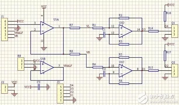
The picture above shows a PWM generation circuit that uses the linear potentiometer (or linear Hall element) on the game controller or the model airplane rocker to control the two chassis drive motors. J1 is the socket of the handle, and 123 and 456 are potentiometers in the x and y directions respectively. U1B provides half the power supply voltage, U1A is the voltage follower. The x and y components are synthesized into a voltage signal that controls the speed of the two motors of the left and right wheels. In use, let L=(x+1)y/(x+1.4), R=(x-1)y/(x-0.6), and it has a good effect after experimentation (numbers are only units, not voltage values) . The Schmidt oscillator composed of U1C and U1D converts the voltage into the corresponding PWM signal, which is used to control the power drive circuit. Taking U1D as an example, R1 and R2 form a Schmitt circuit with hysteresis, the upper and lower thresholds are affected by the input voltage, and C1 and R3 form a delay loop, so that the pulse width of the oscillation is controlled by the input voltage. Q1 and Q2 are triodes, which form an inverter and provide differential control signals. See the analysis of the 555 oscillator on the digital circuit textbook for the specific oscillation process.
Seven, stepper motor drive
1. Low-power 4-phase stepper motor drive
The following is a block diagram of a drive circuit:
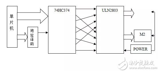
The Darlington tube array ULN2803 takes out the 0, 2, 4, 6 and 1, 3, 5, and 7 bits from the latch to drive two stepper motors. There are several power-on sequences for four-phase stepper motors. : A, B, C, D (4 phases 4 beats); AB, BC, CD, DA (4 phases double 4 beats); A, AB, B, BC, C, CD, D, DA (4 phases 8 beats) ). In order to take into account stability, torque and power consumption, the 4-phase 8-beat method is generally adopted. All of these methods can be realized by cyclic shift (also with regular monitoring), in order to make 4-phase 8-beat easy to achieve, latch The driver and the drive part are cross-connected.
The stepper motor works in four-phase eight-beat mode (that is, the input signal for forward rotation is 1000→1100→0100→0110→0010→0011→0001→1001→1000), and each stepper motor has four signal input terminals , In theory, the output signal to the port can control the work of two stepper motors. The cyclic shift of the register's parity bit is used as the driving end of the two stepping motors. The idea is as follows:
LOOP: MOV A,#1110000B; put 11100000 in the A register
RR A; shift right
AJMP LOOP; rotate right
In this way, the value stored in register A will have the following cycle: 11100000→01110000→00111000→00011100→00001110→00000111→10000011→11000001→11100000, and the odd-numbered bits have the following cycle: 1000→1100→0100→0110→0010→0011→0001→ 1001→1000, the even digits have the following cycle 1100→0100→0110→0010→0011→0001→1001→1000→1100. Output A to the P0 port, then the odd and even bits are exactly the stepper motors we need input signal.
In fact, the action of each motor is different. For this reason, we open up a byte status byte for each motor in the RAM for cyclic shift. In each motor cycle, the byte of each motor is adjusted as needed. Shift, and use the ANL command to synthesize the states of the two motors into one byte to output. At this time, A can control the two motors at the same time.
The speed of the stepper motor is determined by the frequency of the drive pulse. The shift period is different, and the speed of the motor is also different. The motor period mentioned above should take the greatest common divisor of various possible periods. In other words, once The motor cycle is set, and the cycle of each motor shift should be its multiple. In the program, set the corresponding frequency division ratio for the corresponding time of each motor, and use a variable to add one count: every motor Cycle if count variable
In addition, you can also use the traditional look-up table method to drive, the program is a little longer, but also relatively stable, this method is very suitable for three-phase stepper motors.
2. Intelligent driving scheme of stepping motor
Stepping motors have the advantages of being able to be accurately controlled, but they have high power consumption, low efficiency and small torque. If you choose a high-power stepper motor, in order to reduce power consumption, you can take the method of PWM constant current control. The basic idea is to use high frequency PWM with feedback to drive each phase with constant current according to the output power requirements, and the overall current sequence conforms to the rotation sequence. When the torque is small, the current should be reduced in time to reduce power consumption. The circuit realized by this scheme can adopt an independent single-chip microcomputer or CPLD plus a field effect tube drive circuit and a current sampling feedback circuit.
Product Name: Car Charger
Place of Origin: Guangdong, China (Mainland)
Brand Name: OEM
Output Type: DC
Connection: Other
Rated Voltage: 12V-24V
Working Temp: 0-55℃
Weight: 36g
Materials: PC+ABS
Color: White Black
Warranty: 1 year
Suitable for:Most digital devices
SMART PROTECTION & ATTRACTIVE DESIGN ------ Intelligent circuit design protects against short circuiting,over-heating,over-current,and over-charging. Charging stops when battery is full. Car charger with blue LED indicator,which makes it convenient to find exactly where the connection should go; And the light is soft enough not to distract at night.
Dual USB Car Charger Adapter,USB Smart Port Charger ,Car Charger,USB Car Charger For Phone
Shenzhen Waweis Technology Co., Ltd. , https://www.laptopsasdapter.com