1 Introduction
The IX3476 is the latest 4-channel DC-DC converter from Linear Technology. Each channel can drive up to eight 1 A LEDs in series, enabling up to 32 1 A LEDs with up to 96% efficiency. Each of the four channels is controlled by an independent true color PWM signal, allowing independent dimming of each channel with a dimming ratio of up to 1000:1. The fixed frequency and current mode architecture ensures stable operation over a wide supply voltage and output voltage range. The frequency adjustment pin allows the user to program the frequency from 200 kHz to 2 MHz to optimize efficiency while minimizing the size of external components. The thermally enhanced 5 mm x 7 mm QFN package helps solve the compact footprint and footprint of 100 W LED applications.
The LT3476 senses the output current on the high side of the LED and is therefore the most flexible LED driver solution available in buck, boost or buck/boost configurations. With a full scale value of 105 mV, the threshold accuracy of each current monitor is corrected to within 2.5%, and the user can use an external sense resistor to set the output current range for each channel. The four voltage regulators are independently operated by the PWM signals of the corresponding channels. The PWM accurately adjusts the color mixing or dimming ratio of the LED signal source with a dimming ratio of up to 1 000:1.
2, performance characteristics
The LT3476 features: 1 True Color PWMTM dimming for up to 1000:1 dimming ratio; 2 high-voltage side detection for LED current regulation; 3VADJ pin for accurate setting from 10 to 120 mV LED current detection threshold; 4 independent driver channel with 4 1.5 A, 36 V internal NPN switches; 5 frequency adjustment pin range is 200 kHz~2 MHz; 6 conversion efficiency is up to 96%; 7 with open LED Protection; 8 in operation mode, low quiescent current is 22 mA, low quiescent current is less than 10μA in shutdown mode; 9 input voltage range is wide, UIN=2.8~16V; 10 is heat-resistant enhanced type 38 pin 5 mmx7 Mm QFN package.
3, function description
Figure 1 shows the block diagram of the LT3476. The LT3476 is a constant frequency current mode regulator with an internal power switch. At the beginning of each oscillation cycle, the SR latch is set, the main power switch VQ1 is turned on, and the voltage is proportionally increased or decreased with the current of VQ1, and applied to a stable ramp signal, and the final value is fed back to the PWM. The extreme of comparator A2. When the voltage is higher than the input voltage on the A2 negative terminal, the SR latch is reset and the power switch is turned off. The input voltage on the A2 negative terminal is provided by the error amplifier A1, and its magnitude depends on the difference between the voltage across the internal resistor RSET and the voltage across the external current sense resistor RSNS. In this way, Al is set to the correct peak switching current to regulate the current flowing through the RSNS. The output current on VQ1 increases as the output of A1 increases, and decreases as the output of Al decreases.
Figure 1 Block diagram of the LT3476
The current on the RSNS can be adjusted by changing the voltage across RSET through the VADJ input pin. The output current of VQ3 can be adjusted by amplifier A4 to generate a voltage equal to VADJ across RSET and the input voltage on the CAP pin is 1/10 of the VADJ input. When the input voltage to A4 is 1.25 V, the typical voltage limit on RSET is 125 mV. The PWM pin is used to adjust the average current on the RSNS to dim the LED illumination. When the PWM pin is low, VQ1 is disabled and A1 is turned off, so it does not drive the VC pin. At this point, the internal load on all VC pins is disabled, so the charge state of the VC pins is preserved on the external compensation capacitor. When the level on the PWM pin goes from low to high, the current required by the switch will return to the data before the PWM was last converted to low level, which reduces the transient recovery time.
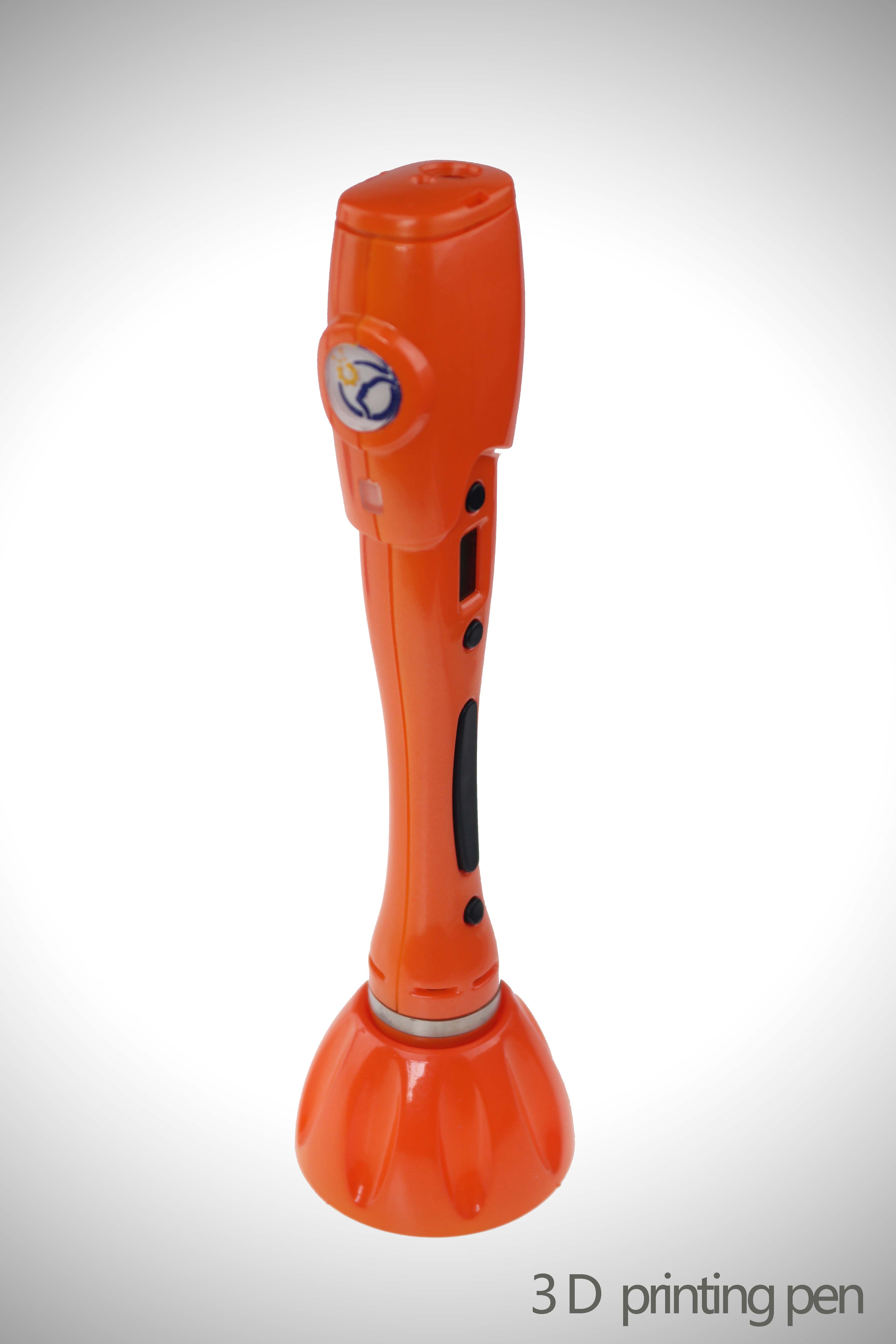
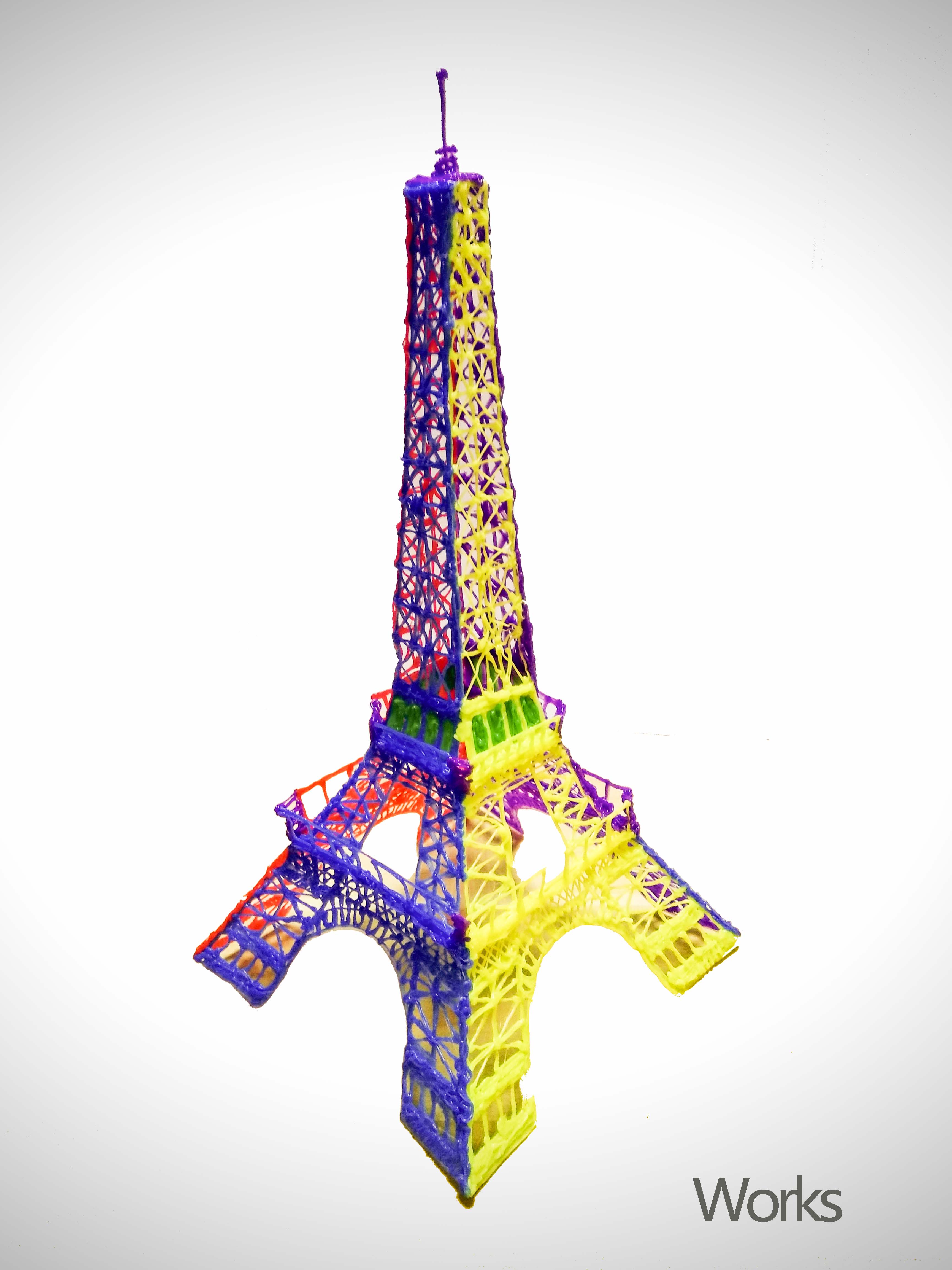
3D printing on the pen machine is mainly used in 3 d printing pen, is made from a special custom Dc Gear Motor, mainly used in 3 d printing pen, pen 3 d printing machine has been updated three generations according to the requirements of product.
3D Printing Motor product introduction:
The 3D Printing Motor is based on the deceleration Motor, coupled with supporting gears and ball bearings.The role of the gear reducer is to provide lower speed and greater torque.At the same time, gear box different deceleration ratio can provide different speed and torque.It's mostly rolling.
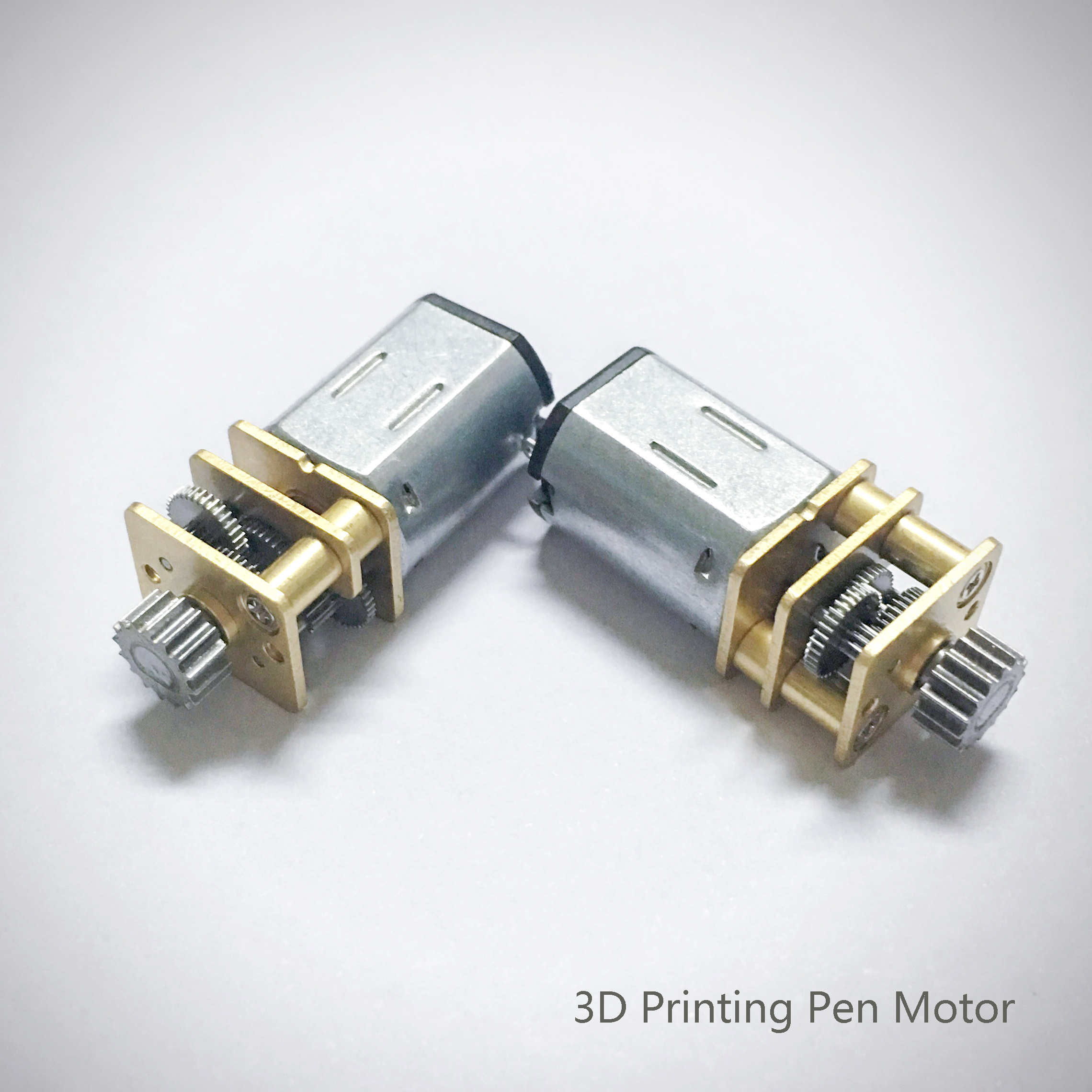
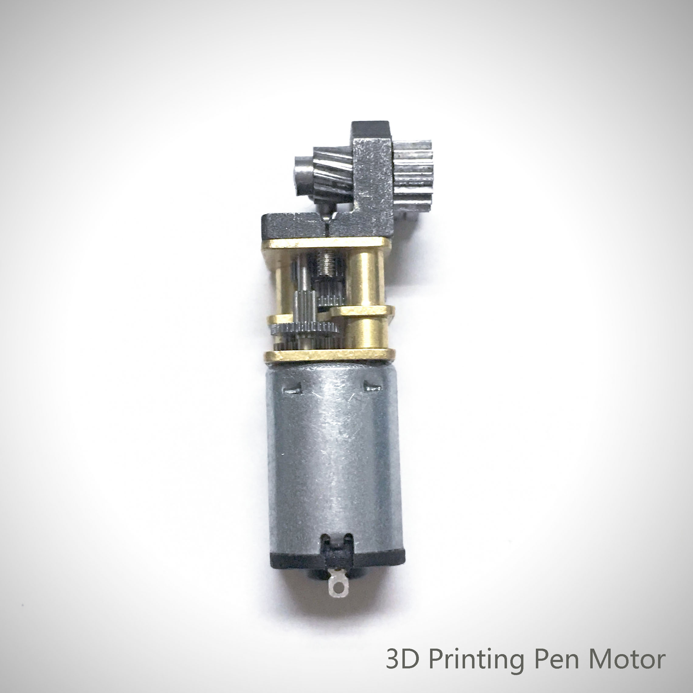
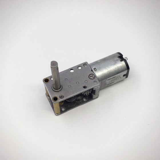
Features: 3D Printing Motor, small size, large torque, low noise, durable, low energy consumption, customized power design, convenient installation and maintenance;
Simplify design and save space.
Features: usually used financial equipment, office equipment, electronic locks, wireless charger, remote control toys, precision instruments and meters, automobile industry, medical equipment, consumer electronics, household appliances, electric glass doors and Windows, etc., wide application range
Method of use: the best stable in horizontal plane, installed on the 3D Printing Motor output shaft parts, cannot use a hammer to knock, knock prone to press into the 3D Printing Motor drive, may cause damage to internal components, and cannot be used in the case of blocked.
Operating temperature range:
3D Printing Motor should be used at a temperature of -10~60℃.
The figures stated in the catalog specifications are based on use at ordinary room temperature catalog specifications re based on use at ordinary room temperature (approximately20~25℃.
If a 3D Printing Motor is used outside the prescribed temperature range,the grease on the gearhead area will become unable to function normally and the motor will become unable to start.Depending on the temperature conditions ,it may be possible to deal with them by changing the grease of the motor's parts.Please feel free to consult with us about this.
Storage temperature range:
3D Printing Motor should be stored ta a temperature of -15~65℃.
In case of storage outside this range,the grease on the gearhead area will become unable to function normally and the motor will become unable to start.
Service life:
The longevity of 3D Printing Motor is greatly affected by the load conditions , the mode of operation,the environment of use ,etc.Therefore,it is necessary to check the conditions under which the product will actually be used .The following conditions will have a negative effect on longevity.Please consult with us should any of them apply.â—Use with a load that exceeds the rated torque
â—Frequent starting
â—Momentary reversals of turning direction
â—Impact loads
â—Long-term continuous operation
â—Forced turning using the output shaft
â—Use in which the permitted overhang load or the permitted thrust load is exceeded
â—A pulse drive ,e.g.,a short break,counter electromotive force,PWM control
â—Use of a voltage that is nonstandard as regards the rated voltage
â—Use outside the prescribed temperature or relative-humidity range,or in a special environment.
â—Please consult with us about these or any other conditions of use that may apply,so that we can be sure that you select the most appropriate model.
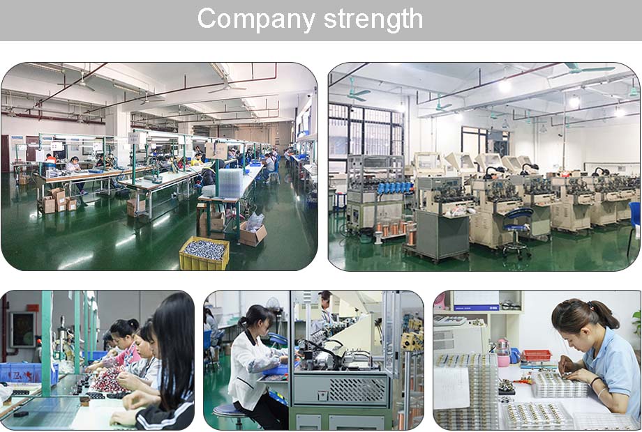
when it come to volume production,we're a major player as well .each month,we rurn out 600000 units,all of which are compliant with the rohs directive.Have any questions or special needed, please contact us, we have the engineer group and best sales department to service to you Looking forward to your inquiry. Welcome to our factory.
3D Printing Motor,3D Printing Gear Motor,3D Printing Pen Motor,3D Printing Spindle Motor
Shenzhen Shunchang Motor Co., LTD. , https://www.scgearmotor.com