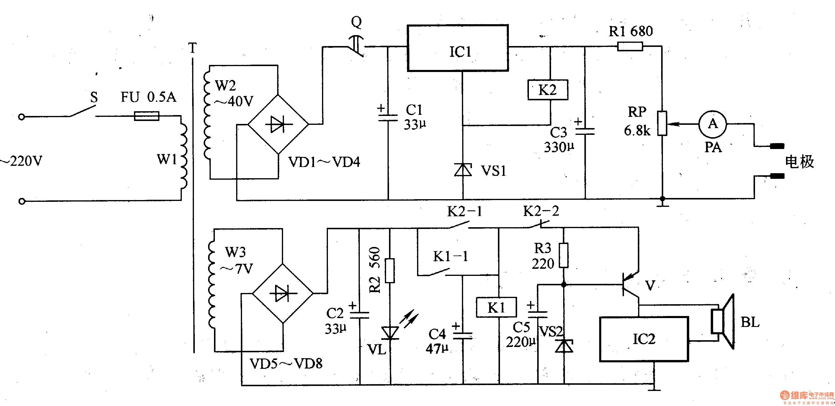
Circuit Operation Principle The bone hyperplasia therapy instrument circuit consists of a power circuit, a timing circuit, a current regulation circuit, a control circuit, and a music report, as shown in Figure 9-22.

The power circuit is composed of a power switch s, a power transformer T, a rectifier diode VDl-VD8, a filter capacitor Cl, a three-terminal integrated voltage regulator ICl, a Zener diode VS1 and the like.
The timing circuit uses 0-60min to mechanically tighten the arm Q.
The control circuit consists of relays K1 and K2.
The current regulating circuit is composed of a potentiometer RP, an ammeter PA, and the like.
The music alarm circuit is composed of a music integrated circuit IC2, a transistor V, a speaker BL, and the like.
The resistor R2 and the light emitting diode VL constitute a power indicating circuit.
After the AC 220V voltage is applied, an AC voltage of 40 V and an AC voltage of 7 V are generated on the windings W2 and W3 on the secondary side of the T, respectively. After the AC 7V voltage is rectified by VD5-VD8 and filtered by C2, VL is lit. Rotate the timer Q (set the treatment time), after the AC 40V voltage is rectified to DC voltage by VDl-VD4, it is added to the input end of ICl through the control contact of timer Q, filtered by Cl and IC1, VS1 After being regulated, it is output from the output of ICl, and is limited by R1 and RP, and then applied to the affected part of the patient through the electrode piece. At the same time, the relay K2 is pulled in, its normally closed contact K2-2 is opened, the normally open contact is fully -1 turned on, the relay K1 is energized, and the normally open contact K1-1 is turned on.
When the treatment time is over, the contact of the timer Q is turned off, the working voltage of the input end of the IC1 is cut off, the relay K2 is released, the normally open contact K2-1 is disconnected, the normally closed contact K2-2 is turned on, and both ends of the C2 are closed. The voltage through Kl's normally open contacts Kl-1 and K2-2 provide working voltage for the music alarm circuit, so that the circuit works, and a music alarm sound is emitted from the speaker BL, prompting the patient that the treatment time has arrived.
Component selection
R1 selects 1/2W carbon membrane resistor for use; R2 and R3 select 1/4W carbon membrane resistor for use.
The RP uses a small solid potentiometer or a carbon film potentiometer.
Both C1 and C3 use aluminum electrolytic capacitors with a withstand voltage of 63V; C2, C4 and C5 are all aluminum electrolytic capacitors with a withstand voltage of 16V.
VDl-VD8 selects 1N4001 silicon rectifier diode for use.
VSl selects lW, l2V lN4742 type Zener diode; VS2 selects 1/2W, 6.8V lN4099 or 2CW55 type Zener diode.
VL uses φ3mm green LED.
V selects S8550 or C8550 silicon PNP transistor.
ICl selects LM7824 or AN7824 type three-terminal integrated voltage regulator; IC2 selects KDl53 type music integrated circuit.
Both K1 and K2 use the Model 1098 9V DC relay.
T selects 15-2OW step-down power transformer.
BL uses 0.25-0.5W, 8Ω electric speakers.
S selects the button self-locking power switch.
The PA uses a 30nA ammeter.
Pv Inverter Energy Meter,Iot Wireless Energy Meter,Ev Charging Meter,Prepaid Energy Meter
Jiangsu Acrel Electrical Manufacturing Co., LTD. , https://www.acrel.com.pk