CATV minimum loss attenuator for 75Ω measurement
Abstract: The CATV system for cable TV based on 75Ω characteristic impedance is tested with a 50Ω laboratory test device. Using a minimum loss impedance conversion circuit (MLP) of 75Ω to 50Ω is a broadband method for accurately measuring power and voltage. This article introduces the resistance network required for a minimum loss impedance conversion circuit. At the same time, the minimum loss impedance conversion circuit equation derived from the usual signal source and load impedance is given.
IntroductionThe minimum loss impedance conversion circuit can be used to measure broadband 75Ω circuits such as CATV tuning ICs, cable upstream amplifiers, and satellite DBS tuning ICs using 50Ω test equipment. When using the minimum loss impedance conversion circuit, you must know whether to use the voltage loss or power loss of the MLP. Due to impedance conversion, the amount of power loss in a minimum loss impedance conversion circuit is different from voltage loss. Obviously, the power loss used for power measurement and the impedance conversion from any direction are the same. The voltage loss used for voltage measurement differs depending on the direction of impedance transformation.
Summary of MLP characteristics from 75Ω to 50Ω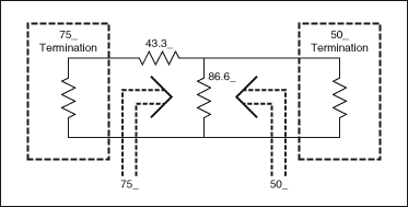
Figure 1. 75Ω to 50Ω minimum loss impedance conversion circuit
Figure 1 shows the conversion of 75Ω to 50Ω MLP. The 75Ω 'end can be regarded as a resistance network of a 75Ω device. Similarly, the 50Ω terminal can be regarded as a resistance network of a 50Ω device.
Table 1 shows that the value of power attenuation is the same when changing from 75Ω to 50Ω or from 50Ω to 75Ω. However, the value of voltage loss when changing from 75Ω to 50Ω is greater than the value of voltage loss when changing from 50Ω to 75Ω.
Table 1. Power and voltage losses of 75Ω to 50Ω minimum loss impedance conversion circuit.
| MLP Impedance TransformaTIon (Ω to Ω) | Power Loss (dB) | Voltage Loss (dB) |
| 75 to 50 | -5.72 | -7.48 |
| 50 to 75 | -5.72 | -3.96 |
| (50 to 75) + (75 to 50) | -11.44 | -11.44 |
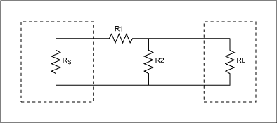
Figure 2. Minimum loss impedance conversion circuit
Figure 2 shows the minimum loss impedance conversion circuit with signal source impedance RS and load impedance RL. An L-type attenuator is used to match high impedance RS to low impedance RL. (Figure 2 assumes RS> RL.) The resistance value of this minimum loss impedance conversion circuit is determined by Equation 1 and Equation 2 [1]. 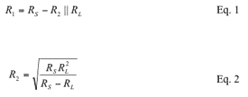
The signal path of the minimum loss impedance conversion circuit shown in Figure 3 is from high impedance to low impedance, that is, from the left side to the right side of the circuit. 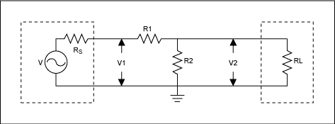
Figure 3. The signal path of the minimum power attenuator from high impedance to low impedance.
In the CATV system, the signal level is measured by the voltage unit dBmV [2], that is, the decibel value relative to 1mV. When the signal level is expressed by the voltage unit, the voltage loss of the MLP is used. According to Figure 3, the following common derivations are derived MLP voltage loss equation, and assume RS> RL.
According to Figure 3: 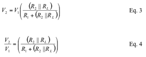
The voltage loss is expressed in dB as: 
Substitute Equation 4 into Equation 5: 
Equation 6.1 is the voltage loss equation expressed by RS and RL, which is the result obtained by substituting Equation 1 and Equation 2 into Equation 6. 
When the signal level uses power units such as dBm, MLP power loss is used. dBm is the decibel value relative to 1mW. The unit for measuring the signal level of a typical test device is dBm.
The equation for MLP power loss comes from the following, Figure 3 and Figure 4, assuming RS> RL. The original equation indicates that the power loss consists of voltage plus a resistance ratio. The power loss can be calculated by the ratio of the delivered power to the available power [3] [4]. 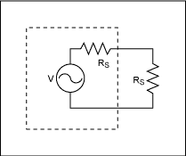
Figure 4. Available power that perfectly matches the load
Available power, PA, is the power obtained when the load is fully matched, as shown in Figure 4. 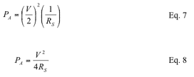
As can be seen from Figure 3, the power delivered to the load, PD, is: 
V2 can be expressed as: 
Substitute Equation 10 into Equation 9: 
The power loss can be expressed in dB as: 
Substitute Equation 8 and Equation 11 into Equation 12: 
According to Figure 3, for a perfectly matched MLP: 
Substitute Equation 16 into Equation 15: 
Compare Equation 18 and Equation 6 to observe the difference between power loss and voltage loss. The power loss is equal to the voltage loss plus a logarithmic sum of the impedance ratio terms.
Equation 18.1 is the power loss equation expressed by RS and RL, which is the result of substituting Equation 1 and Equation 2 into Equation 18: 
In order to maintain the consistency of the discussion when discussing the signal path from low to high impedance, the position of RS and RL in the circuit shown in Figure 5 is the same as that in Figure 3, although the signal now passes through the MLP in the opposite direction. 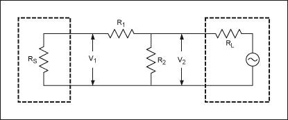
Figure 5. MLP from low-impedance to high-impedance signal path
According to Figure 5: 
The voltage loss can be expressed in dB as: 
Substitute Equation 20 into Equation 21: 
Use RS and RL to express the equation of voltage loss, that is, substituting Equation 1 and Equation 2 into Equation 22. 
From Figure 5, the power loss matched to the signal source and load impedance: 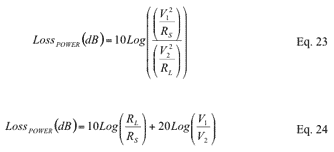
Substitute equation 20 into equation 24. 
Still using only RS and RL to express the power loss equation, substituting Equation 1 and Equation 2 into Equation 25. 
Compare Equation 25 and Equation 22 to observe the difference between the power loss and voltage loss equations. For the signal path from low resistance to high resistance, the power loss is equal to the logarithm of the voltage loss and the resistance ratio.
The resistance value of the minimum loss impedance conversion circuit of 75Ω to 50Ω can be determined by referring to the equation of MLP shown in FIG. 2 above. Select RS and RL to be 75Ω and 50Ω respectively. This also satisfies the assumption of RS> RL. 
From Equation 1: 
Use Equation 6 to determine the voltage loss of the 75Ω to 50Ω signal path. 
Use Equation 18 to determine the power loss of the 75Ω to 50Ω signal path. 
Use Equation 22 to determine the voltage loss of the 50Ω to 75Ω signal path. 
Use Equation 25 to determine the power loss of the 50Ω to 75Ω signal path. 
Note that the power loss is the same when the signal passes in either direction, but the voltage loss differs depending on the signal direction. Similarly, the difference between power loss and voltage loss is attributed to the difference in resistance ratio terms.
The power loss and voltage loss of the minimum loss impedance conversion circuit are different due to the difference between the signal source impedance and the load impedance. Power loss is equal to the logarithmic sum of voltage loss and a resistance ratio term.
When the signal passes in either direction, the power loss is the same. However, when the signal goes from a high-impedance signal source to a low-impedance load, the voltage loss is much larger.
When making dBmV, dBµV or dBV or any voltage-related measurements, use voltage loss. When making dBm or any power-related measurements, use power loss
What is an outdoor wireless access Point?
Outdoor Wireless Access Points (aps) are wireless networking devices designed to provide Wi-Fi coverage in outdoor environments and are often used in industrial and corporate environments that require outdoor Wi-Fi access, as well as in public Spaces such as parks, stadiums, campuses, and outdoor event venues.
Outdoor wireless access points are built with a variety of weather conditions and tolerance to high temperatures in mind, so they are often equipped with weatherproof enclosures to protect internal components from moisture, dust, and other environmental elements. In addition, outdoor wireless access points are equipped with high-gain antennas that enable long-range coverage while simultaneously supporting multiple devices. Some outdoor wireless access points also have grid networks that connect a large number of wireless access points to provide seamless Wi-Fi coverage over a wide area. To protect the security of the network, outdoor wireless access points are also equipped with advanced security features such as WPA3 encryption and guest access restriction. As an important component of outdoor Wi-Fi infrastructure, outdoor wireless access points provide a reliable and secure connection within a certain range of the external environment.
Why are outdoor wireless access points important?
Here's why:
In order to provide reliable and fast Wi-Fi coverage in outdoor environments, outdoor wireless access points must be equipped to cope with the increasing use of mobile devices and meet the wireless connectivity needs of public places. This will support individuals to stay connected, allowing them to use the Internet in public Spaces such as parks, stadiums and universities.
For many organizations and industries, outdoor Wi-Fi connectivity is essential for daily operations. For inventory management and control systems, wireless facilities and warehouses must use wireless communication. These systems must be supported by wireless access points.
Wireless access points can support new applications such as outdoor video surveillance, smart lighting and environmental monitoring. Without outdoor wireless access points, many applications that require wireless connectivity will be difficult to sustain.
Visitors expect Wi-Fi connectivity in public areas such as parks and stadiums. Businesses that provide outdoor Wi-Fi can significantly enhance guest interaction and improve the overall customer experience.
All in all, outdoor wireless access points are equally important to businesses and companies because they allow them to reach out far beyond their original physical premises, reaching out to potential audiences that would otherwise be out of reach.
What are the important characteristics of outdoor wireless access points?
The following characteristics of an outdoor wireless access point are important:
Weatherproof and durable design: Outdoor wireless access points must be able to withstand harsh weather conditions and extreme temperatures. In addition, a weatherproof case is required to protect internal components from moisture, dust, and other environmental elements.
High-speed connectivity: In order to provide service to a large number of users and devices, outdoor wireless access points should provide high-speed connectivity.
Advanced Features: To provide high performance and powerful support for a wide range of devices, outdoor wireless access points should have advanced features including beamforming, MU-MIMO technology, and grid networking.
Simple installation and management: Outdoor wireless access points should be built with centralized management and monitoring capabilities backed by a cloud-based platform for easy installation and management.
Power options: Depending on the deployment area and power availability, the outdoor wireless access point should accept multiple power sources, such as PoE (Power over Ethernet) or direct AC power.
Security: To protect the network and users' data, outdoor wireless access points should include security features such as WPA3 encryption and guest access restrictions.
Customization: To accommodate diverse deployment Settings and extend coverage, outdoor wireless access points should include retrofit options including installation kits and antennas.
Simply put, outdoor wireless access points should be built from the outset to ensure that they provide reliable, high-performance wireless connectivity in demanding outdoor environments, while ensuring that they are easy to install, manage, and provide advanced features and customization capabilities.
Outdoor Access Point,Wifi 5 Outdoor Wireless Ap,Wifi 6 Outdoor Wireless Ap,1Km 300Mbps Outdoor Access Point
Shenzhen MovingComm Technology Co., Ltd. , https://www.mcrouters.com