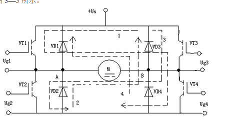
The main circuit of the reversible PWM converter has many forms, the most commonly used is the bridge type (also known as H-type) circuit

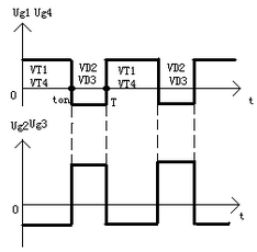
4 driving voltage waveforms of bipolar control reversible PEM converter


The relationship between them is: Ug1≠Ug4=_Ug2=-Ug3. In one switching cycle, when 0≤tston, Uab=Us, and the armature current id flows along loop 1. When ton≤tT, the driving voltage reverses, id flows through the diode along loop 2, Uab=-Us. Therefore, Uab has a pulse waveform between positive and negative machines in one cycle, which is the origin of the bipolar name.
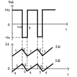
Figure 3-6 also plots the output voltage and current waveforms during bipolar control. 1g is equivalent to "normal load
In the case of pulsating current, the direction of the pulsating current is always positive: 1a is equivalent to a light load situation, and the current can be either positive or negative.
Ten days of pulsation, but the average value is still positive and equal to the load current. The forward and reverse rotation of the motor is reflected in the width k. of the positive and negative pulses of the driving voltage. When the positive pulse is wide, ton> T/2. The average value of Uab is positive, and the motor rotates forward, otherwise, it reverses; if the positive and negative pulses are equal, t=T/2. The half-average output voltage is zero , The motor stops. The waveform shown in Figure 3-6 is when the motor is rotating forward. The average output voltage of the bipolar control reversible PWM converter is;
∪. =≌∪,__T TT三∪;=ζ2t∞_1)∪,T
If the definition of duty cycle Ï and voltage coefficient γ is the same as that of a non-reversible converter, then in a bipolar reversible converter: γ = 2Ï -1 is different from the relationship in a non-reversible converter. When adjusting speed, the adjustable range of Ï is 0~1, correspondingly, y = (-1) ~(+1). When Ï≥1/2, γ is positive, and the motor rotates forward; when Ï is related to the working principle of the reversible PWM converter, the advantages and disadvantages of the reversible PWM converter are discussed. The application of the H-bridge reversible PWM drive circuit based on IR2110
Table Air Purifier,Table Top Air Purifiers,Table Top Air Filter,Tabletop Hepa Filter
CIXI KYFEN ELECTRONICS CO.,LTD, , https://www.kyfengroup.com