For higher IF analog-to-digital converters (ADCs), correct selection of board-level components is a necessary condition for high dynamic performance and wide gain flatness. This technical document describes how to select the input network and simplify the design of single-ended to differential signal conversion with the help of broadband transformers, termination resistors and filter capacitors.
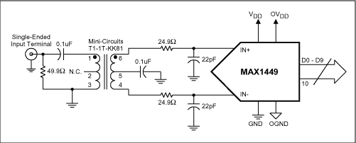
This article takes MAX1449 as an example for explanation and analysis, and gives two possible input configurations. Figure 1 shows a typical AC-coupled, single-ended to differential conversion design. This design uses a broadband transformer (such as Mini-Circuits' T1-1T-KK81 (200MHz)), and the primary side is terminated with a 50Ω resistor and a 25Ω / 22pF filter network. In this configuration, a single-ended input signal with a source impedance of 50Ω is converted into a differential signal by a transformer. 50Ω primary-side termination can achieve a good match between the signal source and the transformer. However, this also means that there is a mismatch between the primary and secondary sides of the transformer. The equivalent resistance of the primary side is 25Ω, but there is a large impedance mismatch on the secondary side. This is because the ADC's 20kΩ input resistance is paralleled with a 22pF capacitor. This will affect the frequency response characteristics of the input network, and ultimately the frequency response characteristics of the converter. The nominal leakage inductance of the transformer is 25nH to 100nH. Combined with a 22pF input filter capacitor, this will produce a resonant frequency:

Resonant frequencies between 110MHz and 215MHz will produce interference spikes in this band.

figure 1.
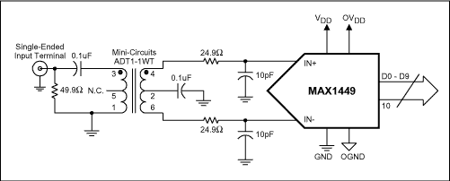
Figure 2 depicts a similar AC-coupled configuration, but it uses a broadband transformer with primary-side termination and better performance (such as Mini-Circuits' ADT1-1WT (800MHz)) and a 25Ω / 10pF filter network. Although the impedance of the ADT1-1WT is 75Ω, the lower leakage inductance raises the -1dB frequency to 400MHz, while the T-1T-KK81's -1dB frequency is only 50MHz.

figure 2.
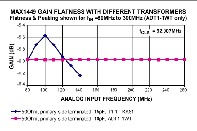
Figure 3 shows the comparison results of the two termination architectures supplemented by transformers and filter network devices. From the figure we can see a significant performance improvement. The input bandwidth of the T1-1T-KK81 transformer (blue line) has a gain fluctuation of approximately 0.5dB between 90MHz and 110MHz, while the input bandwidth of the ADT1-1WT transformer (purple line) maintains a gain fluctuation of 0.1dB within 300MHz. Dynamic range (ADT1-1WT transformer, 50Ω

image 3.
The primary side is terminated, and the input filter capacitor at INP and INN is 10pF). At fIN = 50MHz, the SNR is still 58.4dB. Although Figure 3 only shows the input frequency of 80MHz to 260MHz (ADT1-1WT), laboratory test results show that the input frequency can exceed the 8th order Nyquist frequency within a range of 0.1dB of gain fluctuation.
Improving transformer secondary impedance matching can further improve gain flatness. One method is to use secondary termination instead of primary termination. This method will be discussed in other application notes. This solution is based on Maxim's recently introduced MAX1122 / 23/24 series for input network design and analysis. Please refer to the following application note link for details on primary and secondary termination.
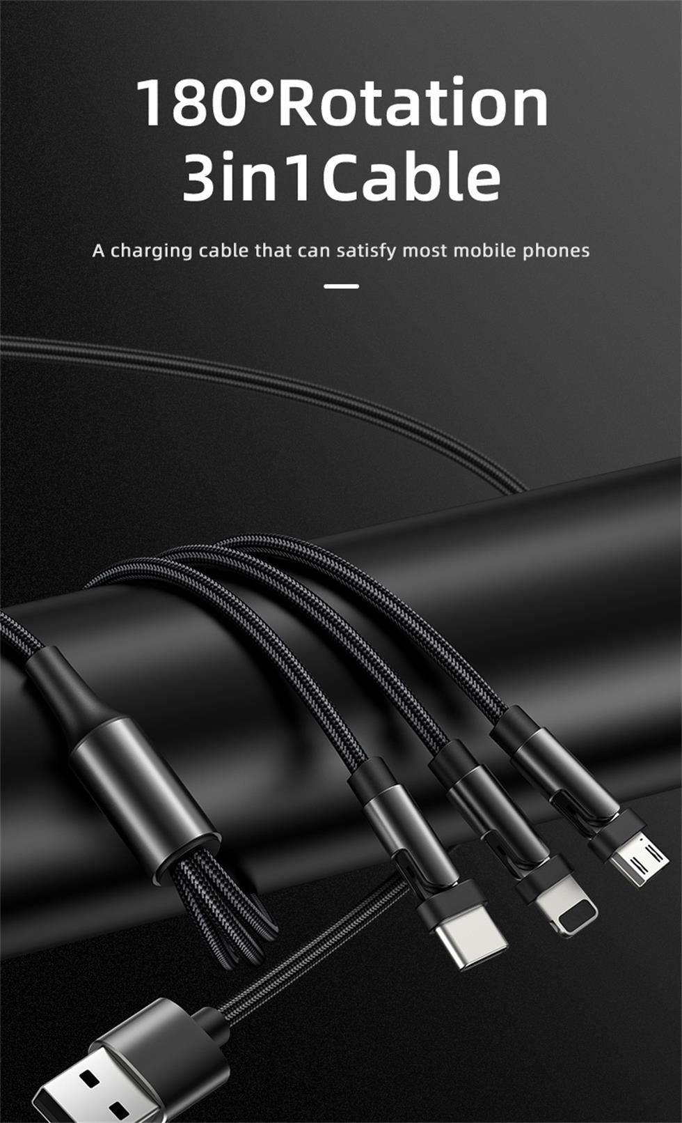
Nowadays, the function and appearance of mobile phones are similar, but the charging interface is not unified. The Android camp has Micro USB and Type-C ports, while the iPhone camp has Lightning. Different charging ports use different charging cables, which is very unfriendly for users who often need to use multiple phones. To solve this awkward situation, the three-in-one data cable was born. What is the three-in-one data cable? Three-in-one data cable means that one data cable includes Micro Usb Cable, USB Cable For Iphone and Usb Cable Type C. So one data cable can be used by all mobile phones.
Three-in-one data line is also known as multifunctional data cable. In the original data cable, the combination scheme is added, and the combination PCB is configured, which can support a variety of equipment and avoid the trouble of frequently looking for data line. It combines Lightning, a 30-pin port, and a Micro USB port, and is compatible with multiple devices. It can connect to any smartphone or tablet, including iPhone, iPad, Samsung, etc.
From the technical point of view, the three-in-one data cable does have a strong advantage. With continuous development and improvement, three in one data cable products in the original data cable appearance with woven cloth, will also add a light color on the three in one data cable, so that the data cable function is stronger and more exquisite, more and more people accept and buy. In the era of big data,the 3 In 1 Usb Cable can be said to have deeply affected our work and life. We believe that with the technical development of 3-in-1 mobile phone data cable, it will bring us more convenient transmission experience.

3 In 1 Usb Cable,3 In 1 Data Cable,3 In 1 Usb C Cable,3 In 1 Universal Cable
Henan Yijiao Trading Co., Ltd , https://www.yjusbcable.com