Overview:
At present, the data line plug-in charging is commonly used, and the charging method of the data line interface often has a bad touch. The wireless charger design described in this article uses the principle of electromagnetic induction to charge electronic products such as smart phones and wearable devices.
1. System Overview
1.1 Current charging mode In today's rapid development of electronic technology, the number of mobile phone users worldwide has reached 3.3 billion. Together with other peripheral electronic products such as MP3 and MP4, less than 2 people have an average charge. Portable electronics. At present, data line plug-in charging is commonly used. This type of charging method has a bad touch phenomenon when the data line interface is used for a long time, and the individual chargers are not widely adapted, because different types of electronic products need to use different ones. The charger, when looking for a suitable socket and smoothing the wiring, can be said to be time-consuming and laborious; charging various portable electronic products is a headache. In order to improve the above phenomenon, it is necessary to develop a smart wireless charger.
1.2 Introduction and Advantages of the Works The intelligent wireless charger uses the principle of electromagnetic induction. It is a non-contact charging system that no longer transmits power through wires (charging lines), but wirelessly. There is no physical interface used for charging. Compared with the general charger, it avoids the trouble of plugging or unplugging the battery. It has the working principle of the general charger. The work uses one (charger) to charge multiple (inductive load) and intelligently charge. Design idea; when the wireless charger charges the load, the indicator light will be converted from green light to colorful light, and the mobile phone also correctly displays the charging status and intelligently completes the charging process (the experimental product is a mobile phone). The charger can charge multiple loads at the same time, can automatically sense whether there is load charging, achieve automatic charging, automatically power off 10 seconds after full charge, to achieve intelligent; thus greatly facilitating users. The smart wireless charger is very convenient to use, and a charger can meet the needs of a family. It has the advantages of high promotion and application value, low cost (similar to the price of a general charger), and many other large companies in the world (such as Sony). , Intel, Apple, Philips, etc.) is also in the hot research; smart wireless charging will be the development direction to replace physical plug, will certainly be welcomed and valued by people.
Based on the above ideas, make full use of the knowledge of electronic technology learned, and be carefully guided by the teacher. Design and manufacture smart wireless chargers with the following advantages:
(1) The low-cost circuit is composed of a pulse generating part, a power amplifying part, a filtering part, a comparing part, and a transmitting and receiving part, and each part is composed of only a few small components, and is simple to manufacture.
(2) One-to-many charging one charger can charge multiple loads, one family can purchase one charger to meet the needs of the whole family. As the load increases, the work efficiency will also increase, so it can save power while It can also reduce unnecessary overhead.
(3) Convenience Compared with the general charger, it reduces the trouble of plugging and unplugging, and also avoids the phenomenon that the interface is not applicable, the contact is bad, and the elderly can also be conveniently used.
(4) Intelligent As long as the inductive load is placed on the charger, it can automatically sense the charging. Through the information feedback, when the inductive load is fully charged, the power is automatically turned off to realize the intelligent charging process.
2. Overview of working principle
2.1 System Module The wireless charger uses the principle of electromagnetic induction. A 36.7K pulse frequency is generated by the NE555D chip (because the debug is at the 36.7K frequency, the efficiency is the highest), the IRFP460 power is amplified, so that the transmitting coil generates a magnetic field, and when the receiving coil is close, an induced current is generated, after full-wave rectification and Voltage regulation, get the charging voltage and current required by the load (mobile phone). The current of the transmitting coil will increase with the increase of the inductive load. The load voltage of 0.33 ohm is amplified by 23 times by the operational amplifier, and then the voltage U1 is compared with the reference source Uo after 1N4148 rectification and filtering. When charging, U1 is larger than Uo colorful lights, indicating that charging is in progress; when empty load or full charge, U1 is less than Uo, green light is on, if there is no inductive load after 10 seconds, it will automatically power off; press reset button to restart the charger start up. The specific circuit analysis is as follows:
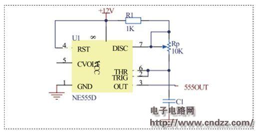
2.1.1 NE555D pulse generator module As shown in Figure 1, according to T = (R1 + Rp) C1, f = 1 / T, adjust Rp to make NE555D output a pulse frequency of 36.7KHZ. 
Figure 1 NE555D pulse generator module
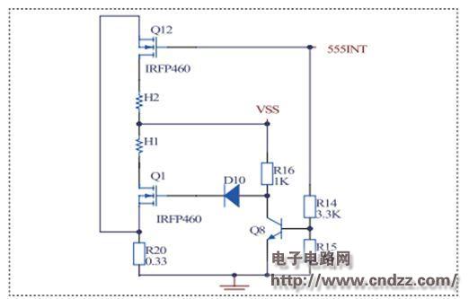
2.1.2 Power amplification and wireless transmission module mainly amplifies a 36.7KHZ pulse power generated by NE555D and transmits it through the transmitting coil. When the pulse is high, Q12 gate is high level, Q12 is on. At this time, Q8 is saturated, Uceq voltage is only 0.67V, Q1 gate voltage is 0 after D10-4148, Q1 is cut off. When the pulse is low, Q8 and Q12 are turned off at the same time, and the current is directly turned on by R16 D10 Q1 and Q1. Throughout the process, both Q1 and Q12 work in an open and closed manner. The circuit is shown in Figure 2: 
Figure 2 Power amplification and wireless transmitter module
2.1.3 Induction coil module As shown in Figure 3, when the induction coil is close to the transmitting coil, an induced current will be generated. After full-wave rectification, according to the charging voltage of different electronic products, different Zener diodes can be selected for voltage regulation. After the current is amplified by the transistor Q100, different electronic products are charged.
2.1.4 Charging detection module When there is an inductive load, the voltage on the R20 (0.33 ohm) resistor will increase. After the amplifier U2A amplifies A=1+R5/R6=23 times, the voltage changes obviously, and then rectifies through 1N4148. Filtering, the voltage U1 and the reference source U are obtained. Compare, U1>U at this time. The op amp output Ui is at a high level, and the colorful lights are blinking; when the inductive load is fully charged (or no load is sensed), U1 < U at this time. The op amp output Ui is low and the green light is on.
(Please read the PDF for details)
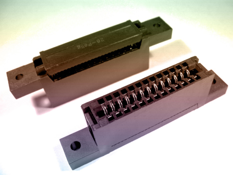
1.ANTENK Card Edge Connectors are precision engineered PCB mount connectors developed to mate with the plated fingers of a printed circuit daughter board. Their bifurcated, cantilever contacts are set in a dual readout configuration and they offer a reliable connection for a wide range of PCB thicknesses. ANTENK`s sturdy solder tails with tapers allow easy insertion and rugged durability
Card Slot Connectors Specification:
*Electrical Characteristitics:
Current Rating;0.5A.
Withstanding Voltage:AC500V r.m.s.
Insulation Resistance:1000Megohms Minimum at DC 500V
Contact Resistance:100Miliohms Maximum.
*Mechanical Characteristics:
Mating Cyeles:5000 Insertions.
*Environmwntal:
Operating Temperture:-40°To+60°
*Material:
1.Housing:HI-Temp plastic UL 94V-0 Rated.
2.Contact:Copper Alloy.
3.Shell:SUS.
*Finish :
1u" Gold plated on conatct area,1u" Gold plated on
solder tails, Base Nickel :50u"Min
*Packing:
Number of connectors:750Pcs/REEL

MATERIAL&FINISH
Insulator:PBT Glass Fiber(UL94V-0)
contact:Brass
Contact:Gold-Plated Over Nickel
SPECIFICATIONS
Current Rating:1A AC,DC
Voltage Rating:250V AC,DC
Temperature Range:-40℃ To+105℃
Contact Resistance:20mΩMin
Insulation Resistance:1000MΩ Min
Withstanding Voltage:500V AC/Min
Video Card Connectors,Card Slot Connectors,Card Edge Slot Connector,CF Card Connector, Edge Card Connector,Memory Card Connector,PC Card Connector,SIM Card Connector,Smart Card Connector
ShenZhen Antenk Electronics Co,Ltd , https://www.antenksocket.com