In the design of high-performance data acquisition systems, people may seldom notice that the biggest obstacle to achieving performance goals usually appears in the signal input channel before the analog-to-digital converter. Before entering the complex mixed signal circuit, the small signal processing circuit is very critical.
In the small signal processing circuit, the noise brought by the amplifier is inevitable. In fact, this will determine the best possible signal-to-noise ratio of the system. In this article, we will use weigh scale and temperature measurement as application examples to discuss how to improve measurement accuracy through high-precision amplifiers in test applications.
Application case analysis1. Application of Weighing Meter
Weighing scales are used in various occasions from bathrooms to factory floors, with full scale ranging from less than 250 pounds to thousands of tons. Weighing gauges are based on thin-film metal strain gauges plus a well-designed metal rod structure. These strain gauges are connected into a traditional bridge structure to achieve maximum sensitivity. It can usually provide a full-scale output of 1~4mV/V, and the maximum output signal with 5V excitation is 20mV.
Under high-performance measurement conditions with a resolution of 1 ounce, to display a weight range of up to 1 ton (2000 lb), we would need more than 30,000 counts. In order to obtain accurate measurements at this resolution, an amplifier that can provide 125 times the signal gain is needed to increase the 20mV output of the A/D converter to 2.5V, and the loop gain needs to exceed 30,000 to ensure that the resolution is satisfied. The linearity of the rate.
2. Temperature sensor
High-precision temperature measurement is another application that is very common and urgently needed for high-resolution data converters. In most cases, the selected sensor is a thermocouple. The K-type scale factor (formed by the joining of a piece of nickel complex alloy and a piece of nickel-aluminum alloy) is about 40uV per degree, while the output of the S-type (formed by the joining of platinum-rhodium alloy and platinum) is about 10uV per degree. It is very important that the nonlinear error must be corrected within the measurement range, which further complicates the measurement work. Other circuit problems may be encountered when using thermocouples, for example, the connection of thermocouples requires protection circuits.
In the entire measurement range, the output of the thermocouple can usually reach 20mV to 50mV, or higher. In the case of using the K-type contact, the measurement accuracy of 0.1 degree resolution (or 10,000 counts) is obtained in the range of 1,000 degrees, and it seems a simple and simple method to make the full-scale measurement equal to 40mV. Other errors include input drift of the operational amplifier and thermocouple nonlinearity errors of 0.25 to 0.5 degrees.
3. Thermopile
Thermopile (thermopile) is a variant of thermocouple. It consists of several thin-film thermocouple contact layers to form a sensor stack. Each metal wiring pair consists of a hidden "cold" edge and a "hot" edge exposed to incident light. "Side composition. It can be used for laser power, heat and flame detection measurements. The full-scale output is usually less than 1mV, and the measured optical output of one-100,000th of the full-scale is equivalent to less than 10 nanovolts. For this application, finding a low-cost, high-gain, low-noise and low-drift amplifier will be a big challenge.
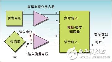
Error analysis affecting accuracyA typical AD converter block diagram is shown in Figure 1. The main error influencing factors include reference voltage error, amplifier error, sensor error, and noise impact on measurement accuracy. Understanding these errors helps design engineers better deal with the design challenges of improving measurement accuracy.

Figure 1: Block diagram of a typical AD converter
1. Reference voltage error
Because the reference voltage is used to compare with the actual measurement value, the actual value of this reference voltage is very important. Periodic calibration or software calibration of the reference voltage is required to correct this basic measurement error. Moreover, a well-designed reference voltage can be used to minimize drift due to temperature. Under conditions exceeding 0°C to 40°C, the error of a temperature coefficient of 100ppm/°C may be 4,000ppm, or 0.4% of the full scale range. We can use software to correct this error, but it will directly reduce the effective range.
2. Amplifier Error
Errors directly imposed on the input signal by the input amplifier will affect the measurement accuracy. Take the pressure component as an example, a 20mV full-scale signal will have a 5% offset, that is, 1mV input bias voltage. This input offset error can directly reduce the measurement accuracy, and it is possible to use software to eliminate this error with an A/D converter with sufficient dynamic range. This error also has a temperature-related component, called input offset drift, which must be carefully considered and corrected. Bias current, also known as input leakage current, can cause direct voltage bias errors on high-impedance sensors or sensor pins or any impedance between the sensor and the amplifier input. For example, if the input bias current is 0.1 microamperes, the voltage drop across a 10 ohm resistor will produce an error of 1 microvolt.
3. Sensor error
Correcting sensor errors can be difficult. Taking the pressure measuring element as an example, although careful linear calibration has been carried out during the production process, the variation of the output ratio coefficient between different devices in the application is still up to 25%. In the above-mentioned weighing example, the reference voltage is usually generated by the excitation of the load cell, resulting in a ratiometric measurement method that can eliminate drift errors. The ratio of the bias current to the bridge current can directly affect the accuracy of the measurement. The impedance, thermopile protection and compensation circuit in the thermocouple make the input leakage current especially important.
4. Noise Impact
Noise has many sources and is usually a decisive factor in the performance of the entire system. Noise from the outside is more difficult to control, including coupling noise from nearby high-speed digital logic circuits, power supplies, fan motors, solenoid valves, and radio frequency EMI. Careful grounding design, shielding technology, and circuit board layout are critical to achieving the expected accuracy. . Choosing a buffer amplifier that introduces the least noise, eliminates externally introduced errors, and has sufficient gain bandwidth is as important as the above-mentioned method of reducing any input errors.
The high-precision amplifier can be evaluated based on the amount of noise introduced. When the measurement is important for a specific application, the amount of noise is usually determined based on the measurement value of the unrestricted bandwidth (broadband) signal, or is determined The value obtained on the bandwidth. The noise specification is usually used as the input reference noise, which is a value measured under the condition of a short circuit between the output and the input, so it is entirely due to the noise generated by the amplifier itself.
When using an A/D converter, background noise is a decisive factor in the available measurement accuracy. When the rated resolution of a device is 24 bits, the actual accuracy achieved by the converter is usually lower due to the limitations caused by noise. For example, the amplifier specifications, manufacturers determine their products based on the noise level, or based on extremely low noise or effective bit (resolution, also known as ENOB). In fact, the effective bit specification is calculated from the RMS value of the noise level, and the very low noise value is based on the peak-to-peak value, which is usually 6.6 times the statistical RMS value. Therefore, the very low noise specification represents the effective resolution of the converter, and the LSB bit remains stable above the background noise. Since this value is based on the ratio of the input range to the measured noise, special attention should be paid to the restrictions in the specifications. For example, the reference voltage and input range may vary from application to application, and the promised ratio in the data sheet may be comparable to the actual ratio. Big difference.
Amplifier solutionWe have learned that many applications require excellent performance. The amplifier is a low-cost device that can effectively correct its own errors, while also ensuring the stability of high-gain configurations. The chopper amplifier is a typical self-correcting amplifier.
At present, a good chopper amplifier can easily achieve an initial offset error of several microvolts and low drift. However, like any amplifier design, it is quite challenging to achieve both low noise and high gain at the same time. As in the above weighing example, the signal gain needs to maintain the accuracy of 100,000 measurement counts. This is equivalent to a gain of at least 12.5 million and a gain of at least 142dB. The noise makes it more difficult to achieve such a high gain in a high-gain circuit.
In short, for these applications, the noise level of an amplifier needs to be in the same range as other errors. All semiconductor amplifiers have 1/f noise, also known as flicker noise, which is a basic phenomenon due to materials. Contrary to frequency, below a specific noise inflection point, the noise density will increase exponentially and become very large at low frequencies. Within the typical signal bandwidth of 200Hz, an amplifier that allows us to maintain 18-bit resolution at a 20mV full-scale signal needs to have a noise density of about 10nV/rt-Hz. Few amplifiers can achieve this combination of low noise and high gain on a single chip at low cost.
To achieve this level of performance, designers can usually design hybrid multi-amplifier systems. This system uses a combination of input amplifiers with high input impedance, an input error correction circuit, and a second (or third) compensation amplifier to achieve the desired gain. These circuits are expensive and difficult to implement. Amplifiers that focus on one parameter often cause serious problems in other areas. For example, JFET input amplifiers are known for high input bias errors. Discrete chopper amplifier circuits have also been implemented, but with high complexity and high cost. The CS3000 series amplifiers introduced by Cirrus Logic have achieved good noise performance. When the chopping is done well, it is particularly beneficial to reduce 1/f noise in low-frequency applications. The CS3000 circuit can eliminate input offset errors and operate at a relatively high clock rate.
Utilizing multiple internal gain stages and finely optimized compensation, the CS3000 series amplifiers provide excellent open-loop gain and an adjustable gain bandwidth of almost 2MHz. However, these devices are internally optimized for signals below 2kHz to minimize power consumption. When used in gain configurations above 50V/V, external compensation is required. It is worth noting that high open-loop gain can achieve two goals: 1. The sensor gain is required to obtain a tiny sensor signal, which can be accurately measured by the A/D converter; 2. The remaining gain needs to maintain dynamic accuracy.
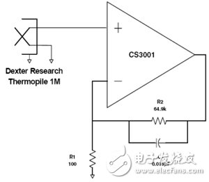
Figure 2 is an example of a thermopile application. When exposed to high levels of infrared radiation, this device can output a full-scale voltage of several millivolts. The gain provided by the CS3001 in this circuit is 650V/V (56dB), and as a result, a full-scale signal of about 1.5V can be generated, with a gain margin of more than 140dB (minimum) to ensure linearity error. In this way, the measurement accuracy of the A/D converter will exceed 17 bits.

Figure 2: Example of thermopile amplifier
Insulated Copper Tube Terminals
Insulated Copper Tube Terminals,High quality insulated terminal,copper tube terminal
Taixing Longyi Terminals Co.,Ltd. , https://www.longyicopperlugs.com