Introduction When you design a circuit board, integrate the MAX3420E with your favorite microcontroller. Power up, plug in the USB, it doesn't work ..., what should I do? This article provides the answer for you.
When debugging a USB peripheral device for the first time, it will face great challenges. To make the MAX3420E work properly, you first need to check according to the following steps.
Check the pins of the USB 'B' type connector. This is the most error-prone-is the view top or bottom? Where is pin 1? If you are not a mechanical engineer, these views will make people feel at a loss. Figures 1 and 2 can help you solve this problem.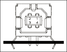
Figure 1. Internal structure of USB Type B connector
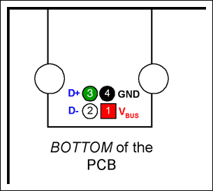
Figure 2. Pin location of the B-type connector, viewed from under the PCB.
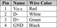
Figure 3. USB cable connector
An ohmmeter should be used to check the connection between the MAX3420E and the USB connector. Pay special attention to D + and D-. The two are easily reversed. Note that there are 33 between the MAX3420E and the D + and D- pins of the connector resistance. For such a small resistance, most instruments that test whether they are connected will emit a "beep" sound. If you need to check the USB cable, please refer to Figure 3.
Reset the processor, connect the cable to the PC USB port, and after the initialization code is executed, stop running before the statement that sets the CONNECT bit. The statement is as follows:
wreg (rUSBCTL, bmCONNECT); // Connect to USB Before executing this statement, D + and D- should both be low. This is because the host side circuit of the cable passes 15k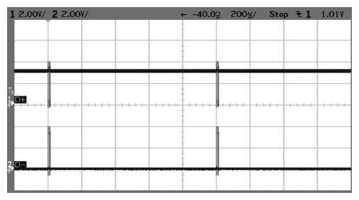
Figure 4. When CONNECT = 1, D + goes high and some bursts appear.
The upper waveform is D +, and the lower one is D-. The burst waveform lasts about 18s and then disappears. D + remains high, D- remains low, and then the following Windows XP message box pops up (Figure 5):
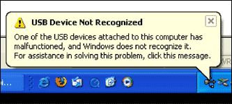
Figure 5. Windows XP prompt message
what happened?
Please note that the program is executed in single steps. All that has been done so far is to connect the D + pull-up resistor. The pull-up prompts the PC that a new USB device has just been inserted, so the PC starts sending signals to the device to determine the device type. This is the pulse signal in FIG. 4. Because the microcontroller code stops running, it will not command the MAX3420E to respond. Since the PC did not receive the response signal, it finally decided (after 18 seconds) to ignore the device. The bus state where D + is high and D- is low is called "USB bus suspend" or "suspend". The host stops sending any signal, and the D + pull-up resistor of the MAX3420E keeps the D + signal high.
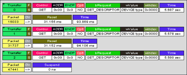
Figure 6. Description of bus operation (NAK not shown)
Figure 6 shows the bus process measured by the USB bus analyzer of LeCroy Instruments (LeCroy merged CATC, CATC is the original manufacturer of the analyzer). When the PC detects that the device is plugged in (CONNECT = 1), it sends out a USB bus reset signal (not shown). Then, in Transfer 0, it issues a "GET_DESCRIPTOR" request to get the "DEVICE" type. After 5.687s, the PC sends a second USB bus reset signal, and then tries 5.578s again, asking for the device descriptor. The PC resets the bus for the third time, tries 5.580s again, then suspends the bus and gives up trying. Since the firmware is not running, the device will not listen to or acknowledge (ACK) PC requests.
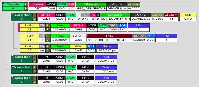
Figure 7. The packet and NAK handshake signal after the first transmission process in Figure 6 is expanded
For clarity, Figure 6 does not show the NAK (non-answer) handshake signal returned by the MAX3420E. Figure 7 expands the first transmission process and displays the data packets in detail. Now you can see that Transfer 0 starts with the following three packets:
The host sends a SETUP packet (63) to the device just connected in this case, USB sending address 0). The host sends a DATA packet (64) containing an 8-byte "opcode". The peripheral device (MAX3420E) sends back an ACK packet (65), confirming that two host packets were received without errors. If you turn on the system containing the MAX3420E, plug in the USB, and set CONNECT = 1 (but no other operations are performed), the MAX3420E will send an ACK handshake packet (the 65-byte packet from step 3 above). The MAX3420E hardware automatically answers the SETUP phase of CONTROL transmission, which is specified by the USB specification.Next, the host starts sending IN requests, starting with TransacTIon 1. For each IN request, the MAX3420E sends back a NAK (non-answer) handshake signal. This is because the program has not yet been run, so the microcontroller connected to the MAX3420E will not receive SUDAV IRQ (Setup Data Ready Interrupt Request).
Note: The MAX3420E sets SUDAV IRQ to indicate that the microcontroller has received the SETUP packet. This information informs the microcontroller that the packet needs to be decoded and sends back the requested data as a response.These IN-NAK processes last for 5.687s, at which time the PC will reset the bus and start the second attempt. The pulse signal in Figure 4 is the IN-NAK process. If you look closely at the oscilloscope, the waveform will change slightly after 5s-this corresponds to a bus reset (D + and D- are both set low for about 30ms), followed by another SETUP packet. Then, IN-NAK continued for another 5s.
For reference: another analyzer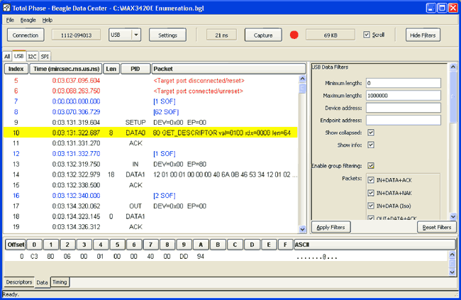
Figure 8. Beagle analyzer
The USB bus analyzer that generates the waveforms in Figures 6 and 7 may exceed your budget. Although this application note assumes that you only have one oscilloscope and ohmmeter, we strongly recommend using a USB bus analyzer during the USB development process. The LeCroy / CATC we use has many advantages, including a friendly interface and rich software. The most important thing is that it enjoys the reputation of the industry standard USB measurement tool. By comparing CATC waveforms to determine the actual situation, many controversial issues (hardware, software, chips, etc.) have been solved. The bus always reflects the situation faithfully.
Fortunately, there are now low-cost USB analyzers. Figure 8 shows a screenshot of Beagle-USB. The Beagle analyzer can display the operation of the bus at a much lower price than LeCroy / CATC. If you compare Index 10 in Figure 8 with the 64-byte data packet in Figure 6, you will find that they show exactly the same SETUP packet.
If the signal in Figure 4 is observed during the inspection process, it can be determined that the connection of the USB connector is correct, and the power supply of the MAX3420E is normal. If the display has not been observed, you can try the following measures: Measure the MAX3420E's RES # pin and make sure it is high. Measure the crystal oscillator to ensure that its oscillation frequency is 12MHz. It must be 12MHz ± 0.25% to meet the USB specification. If the tolerance is exceeded, check whether the connected load capacitance is consistent with the capacitance specified by the parallel resonant crystal (usually 18pF). Check if VCC is 3.3V. Check the system interface voltage VL. Make sure not to exceed 3.6V. If the VCC pin of the MAX3420E is powered by VBUS through a 3.3V regulator, make sure that USB is connected. Otherwise, the VCC of the MAX3420E cannot be powered. Note: Since the operation of the firmware is independent of the USB cable connection, debugging the self-powered design is simpler than the bus-powered design. You can first use an external power supply to power the prototype. If necessary, it can be switched to bus power supply later.The next step is to check whether your controller can successfully communicate with the MAX3420E register set via the SPI bus.
Check rreg () and wreg ().
Writing any program, whether using Maxim ’s example code or writing the code from scratch, requires the use of functions to read and write the MAX3420E register. The following example uses these function prototypes:
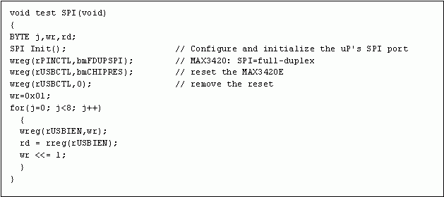
Figure 9. Step by step, check "rd" 8 times to verify the communication between the SPI interface and the MAX3420E.
The test code in Figure 9 first resets the MAX3420E, and then writes 8 bytes each shifted by 1 bit to the USBIEN register. There is a bit in each byte, starting from 00000001, then 00000010, and finally ending with 10000000. Step through the function and check the "rd" value 8 times to determine its value is 0x01, 0x02, 0x04, 0x08, 0x10, 0x20, 0x40 and 0x80. If so, you can be sure that the write and read operations of the SPI interface register are normal. If you can write to the USBIEN register and read back its contents reliably, you can read and write all MAX3420E registers.
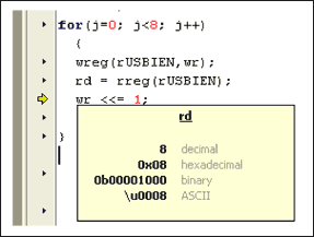
Figure 10. Rowley CrossStudio development tool using MAXQ2000 microcontroller, single-step execution, check variable values. Point the cursor to "rd" and its value will pop up.
Figure 10 shows a screen shot of using CrossStudio to debug a MAXQ2000 microcontroller. When you point the cursor to the "rd" variable, a pop-up window will be activated (the cursor is not shown in the screenshot). When stepping through code, you can view any variable in this way.
The test code first sets the SPI port of the microprocessor. The SPI_Init () function is different for each microprocessor type and specific IO pin assignment. Then, the code writes 0x10 to the PINCTL register to set the MAX3420E SPI interface to full-duplex operating mode. This will set the FDUPSPI bit. The code sets the CHIPRES bit and then clears it to put the MAX3420E in a known state. It is recommended to include the chip reset function at the beginning of the code so that the MAX3420E is in a known state at the beginning of each debug cycle.
If the code in Figure 10 does not produce the correct result, you should check the SPI signal to determine whether it is working properly.
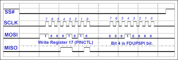
Figure 11. Perform the first wreg () call
The first wreg () call in the test program test_SPI () writes a value of 0x10 to register 17 of the MAX3420E. The waveform of the SPI bus should be consistent with that shown in Figure 11.
Note: The waveform shown in Figure 11 uses SPI mode (0,0). Sampling SPI data on the rising edge of SCLK, the idle level of SCLK is low. Different SPI interface, the displayed waveform will have different pulse duration, but the value corresponding to the rising edge of SCLK should be the same.The first byte of each access to the SPI is the command byte, and its byte format is shown in Figure 12. Note the MOSI waveform corresponding to the rising edge of the previous part of SLCK in Figure 11. Bit pattern 10001010 specifies register 17 (bits 7 to 3 are 10001 and the value is 17). Similarly, the first bit is high, indicating a write operation. The bit pattern of the second byte is 00010000. This is the data written to register 17, which is 0x10 (only the 4th FDUPSPI register bit is set). Therefore, this SPI access writes 0x10 to register 17 and sets the FDUPSPI bit.

Figure 12. MAX3420E command byte format
A simple way to get these waveforms is to set the oscilloscope or logic analyzer to trigger on the falling edge of SS # and single-step the wreg () call.

Figure 13. Writing to the USBIEN register for the first time (test_SPI function)
The next statement in test_SPI () is the rreg () function. When entering the loop body for the first time, write the value 0x01 to the USBIEN register, as shown in Figure 13.
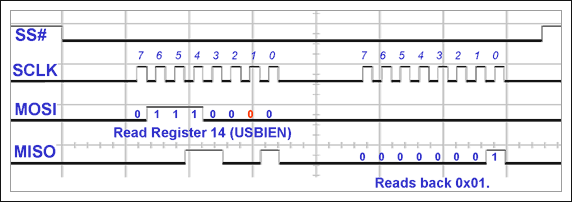
Figure 14. The first call to the rreg () function
Then, the test_SPI () function reads back the value of the USBIEN register and should be equal to 1 the first time through the loop body (Figure 14). Each time through the loop body, the written and read-back bits should move one SCLK edge to the left.
After the MAX3420E register write and read operations are verified, the program can be further debugged. All the inspection steps so far are "integrity checks". Now, we begin the first step of actually handling the USB communication function: the processor needs to respond to different MAX3420E interrupt request bits.
The IRQ bit setting seems that the MAX3420E will set the interrupt request bit only after USB bus communication starts. In fact, when the MAX3420E is powered on, there will be an IRQ bit, and when the USB cable is plugged in and CONNECT = 1, other IRQ bits will be set. The following describes the interrupt request of the startup process.Completing the reset When the MAX3420E completes the reset, even if the USB is not inserted, some interrupt request bits will be set. These bits are:
EPIRQ register:
The initial value of IN3BAVIRQ IN2BAVIRQ IN0BAVIRQ EPIRQ register should be 0x19. The MAX3420E sets these three IRQ bits, indicating that the three IN endpoint FIFOs are ready to load data. BAV stands for "Buffer Available".USBIRQ register:
The initial value of the OSCOKIRQ USBIRQ register should be 0x01. At power-up, the MAX3420E starts its on-chip oscillator. After the oscillator has stabilized, the MAX3420E sets the OSCOKIRQ bit, indicating that it is ready to work. If the program fails the OSCOKIRQ bit check, make sure that the VCC pin voltage is 3.3V. VCC powers the oscillator. Note: The MAX3420E IRQ register bit can be effectively set regardless of whether its corresponding enable bit (in the EPIEN and USBIEN registers) is set. The enable bit determines whether to transfer the request bit to the logic circuit driving the INT pin. See application note 3661, MAX3420E Interrupt System for more detailed information.After plugging in the USB (CONNECT = 0), even if the USB is not communicating, some USBIRQ bits will still be set. The EPIRQ bit is the same as above, but more USBIRQ bits will be set:
USBIRQ register:
OSCOKIRQ VBUSIRQ (possible) The VBUSIRQ bit instructs the MAX3420E to detect the insertion of the USB cable by detecting the 5V signal on the VBCOMP pin. This assumes that you have connected the VBUS pin of the USB connector to the input pin of the MAX3420E microcontroller (VBUS comparator). Note: It is optional that the VBUS pin of the USB connector is connected to the VBCOMP input pin of the MAX3420E. The VBCOMP pin does not supply power to the MAX3420E. It is only connected to the internal VBUS comparator.After setting CONNECT = 1, connecting the USB causes the host to issue a bus reset signal, generate a Get_Descriptor-Device request, and finally suspend the bus. These operations will set more IRQ bits in the USBIRQ register. Note that a USB bus reset will clear the VBUSIRQ bit.
EPIRQ register:
IN3BAVIRQ IN2BAVIRQ IN0BAVIRQ SUDAVIRQ (after communication starts) USBIRQ register: OSCOKIRQ URESIRQ URESDNIRQ SUSPIRQ (Finally) If VBUS is connected to the VBCOMP pin, the USBIRQ register reads 0x8D and lasts about 20s. Then the host becomes suspended and the reading becomes 0x9D.The next situation will depend on your code. If the situation you observe is consistent with the previous one, it means that the system is normal and you can continue to check your code.
Debugging method: The interruption is triggered through 3 steps. The remaining check is to ensure that the firmware can correctly respond to different USB request commands sent by the PC, and the corresponding signal is given by the MAX3420E. If you start the program and nothing happens after plugging in the USB (a Windows USB error message may appear), then your program may not be processing the interrupt. The following debugging methods can help solve these interruptions.Step 1: Polling the IRQ bit First, write the code to directly poll the IRQ bit. When the IRQ bit of interest is set, make the processor perform the corresponding operation. Even if the main program loops for direct polling, it is best to enable interrupts (each IEN bit = 1 and IE = 1). In this way, the MAX3420E INT pin can be observed to understand its working condition. This step effectively cancels the microcontroller interrupt system (and code) check, allowing you to focus on achieving the correct USB function. When continuously reading the EPIRQ and USBIRQ registers, there is no need to worry about wasted SPI cycles-the purpose of this step is to make the USB work properly.
Step 2: Polling the INT pin status Once the USB is working properly, proceed to the second step, modify the program to poll the MAX3420E INT pin status, and check the suspended interrupt. If the program has been verified in step 1, then some code in the main loop of the program has been reading the EPIRQ and USBIRQ registers to check the suspended interrupt. Insert a statement polling the microcontroller interrupt pin status (connected to the MAX3420E INT pin) to modify the continuous check in step 1. If the MAX3420E INT pin does not generate an interrupt, you can skip the statement to read the EPIRQ and USBIRQ registers. This simple check method greatly reduces the SPI data traffic between the microcontroller and the MAX3420E, because it is only tested when the IRQ bit is set.
Step 3: Check the interrupt procedure of the microcontroller. Step 3 and the last step are to integrate the MAX3420E into the interrupt system of the microprocessor. This usually involves writing an interrupt vector to automatically direct the program execution location to the MAX3420E handler.
| Model | Nominal Voltage | Nominal Capacity | Nominal impedance | Dimension | Charge-discharge standard | Approx Weight | |||
| (V) | (mAh) | (mQ) | Diameter | Height | Charge | Discharge | ≈g | ||
| ICR10220 | 3.7 | 130 | <150 | 10 | 22 | 0.5C-1C | 0.5C-1C | 4.1 | |
| ICR10440 | 3.7 | 350 | <120 | 10 | 44 | 0.5C-1C | 0.5C-1C | 9 | |
| ICR14430 | 3.7 | 650 | <100 | 13.8 | 42.8 | 0.5C-1C | 0.5C-1C | 17 | |
| ICR14500 | 3.7 | 900 | <80 | 14 | 50 | 0.5C-1C | 0.5C-1C | 19.5 | |
| ICR17280 | 3.7 | 600 | <100 | 16.3 | 28 | 0.5C-1C | 0.5C-1C | 15 | |
| ICR17335 | 3.7 | 700 | <100 | 16.3 | 33.5 | 0.5C-1C | 0.5C-1C | 18 | |
| ICR18500 | 3.7 | 1400 | <70 | 18.1 | 50 | 0.5C-1C | 0.5C-1C | 33 | |
| ICR18650 | 3.7 | 2000 | <50 | 18.1 | 64.8 | 0.5C-1C | 0.5C-1C | 45 | |
| ICR18650P | 3.7 | 2000 | <40 | 18.1 | 65 | 0.5C-1C | 3C-5C | 45 | |
| ICR18650P | 3.7 | 2200 | <40 | 18.1 | 65 | 0.5C-1C | 3C-5C | 45 | |
| ICR18650 | 3.7 | 2600 | <70 | 18.1 | 64.8 | 0.5C-1C | 0.5C-1C | 45 | |
| ICR26650 | 3.7 | 3500 | <30 | 26 | 65.5 | 0.5C-1C | 0.5C-1C | 85 | |
| ICR26650P | 3.7 | 5000 | <30 | 26 | 65.5 | 0.5C-1C | 0.5C-1C | 85 | |
| ICR18650P | 3.7 | 1500 | <15 | 18.1 | 64.8 | 1C | 10C-15C | 47 | |
| ICR26650P | 3.7 | 2200 | <15 | 26 | 64.8 | 1C | 10C-15C | 64 | |
| IFR14430E | 3.2 | 400 | <115 | 13.8 | 43 | 0.5C-1C | 0.5C-1C | 15 | |
| IFR14500E | 3.2 | 400 | <95 | 13.8 | 50.2 | 0.5C-1C | 0.5C-1C | 15.5 | |
| IFR14500E | 3.2 | 650 | <80 | 13.8 | 50.2 | 0.5C-1C | 0.5C-1C | 17.8 | |
| IFR18500E | 3.2 | 600 | <80 | 18 | 50 | 0.5C-1C | 0.5C-1C | 19.5 | |
| IFR18500E | 3.2 | 1200 | <80 | 18 | 64.8 | 0.5C-1C | 0.5C-1C | 30.4 | |
| IFR18650E | 3.2 | 1500 | <65 | 18 | 64.8 | 0.5C-1C | 0.5C-1C | 40.5 | |
| IFR18650E | 3.2 | 1700 | <80 | 18 | 65.3 | 0.5C-1C | 0.5C-1C | 41.2 | |
| IFR26650E | 3.2 | 3400 | <20 | 26 | 65.3 | 0.5C-1C | 0.5C-1C | 87 | |
| IFR18650P | 3.2 | 1100 | <20 | 18 | 65.3 | 1-3C | 10-25C | 40 | |
| IFR26650P | 3.2 | 2400 | <20 | 26 | 65.3 | 1-3C | 10-25C | 82 | |
3.6V Cylindrical Battery,3.6V 600Mah Ni-Cd Battery,3.6V 800Mah Ni-Mh Battery,Ni-Mh Battery 3.6V 800Mah
Langrui Energy (Shenzhen) Co.,Ltd , https://www.langruienergy.com