Application of SiC device in aviation secondary power supply
introduction
It is well known that during the flight, use and parking of the aircraft, the climatic conditions around it vary widely and change rapidly. Therefore, the working conditions of the aviation electrical equipment are more complicated than those of the ground industrial equipment, and thus the requirements for the aircraft power system are very high.
The secondary power source is an important power conversion device in the power system, mainly including: aeronautical static converter, transformer rectifier, straight converter, and motor driver. The secondary secondary power supply has a harsh working environment and has extremely stringent requirements for performance, reliability, weight, size and energy consumption. At present, the aviation secondary power source is mainly composed of a power conversion device based on Si devices. However, due to the development of Si power electronic devices in the past 60 years, its performance is close to its theoretical limit, and it is difficult to further increase it, which has become one of the bottlenecks restricting the further improvement of aviation secondary power supply.
Through the efforts of researchers, the wide band gap semiconductor materials represented by SiC have gradually demonstrated their excellent performance. SiC power devices are resistant to high temperatures, radiation, high breakdown voltage and operating frequency, and are suitable for operation under harsh conditions. Compared to conventional Si power devices, SiC power devices can significantly reduce power consumption. Therefore, the size and weight of the power electronic device can be greatly reduced, and the reliability can be improved, which has an extremely broad application prospect in the secondary secondary power supply.
2 SiC device superiority and development profile
As one of the most widely used wide-bandgap semiconductor materials, SiC is known as the third-generation semiconductor after Si and GaAs, and has broad development prospects in the manufacture of power electronic devices. Table 1 compares the electrical properties of SiC wide bandgap semiconductor materials with Si materials.
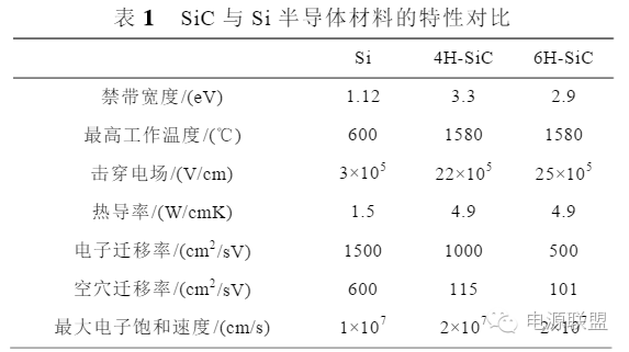
It can be seen from Table 1:
1) SiC has a large forbidden band width
Since the forbidden band width of the semiconductor material determines the operating temperature of the device, the larger the forbidden band width, the higher the operating temperature of the device. Therefore, SiC devices can operate at temperatures up to 600 ° C and have excellent radiation resistance. High-temperature integrated circuits operating at 350~500°C will be widely used in many aspects such as aerospace equipment (electrical automation of turbine engines and aircraft), nuclear energy instruments, satellites, space probes, geothermal wells, etc.
2) High breakdown field strength of SiC
The breakdown electric field of SiC is about 2.5 MV/cm, which is about 10 times that of Si material. This allows SiC power semiconductor devices to operate at much higher voltages than comparable Si devices. For example, Si Schottky diodes have a maximum blocking voltage of one to two hundred volts, while SiC Schottky diodes have a blocking voltage of up to 1700V. Therefore, the high breakdown field strength of SiC makes it easier to achieve the high voltage resistance requirements of power semiconductor devices in aviation systems. For example, PIN can be used to make pin diodes and IGBTs with high breakdown voltage.
3) The specific on-resistance of SiC devices is small
The specific on-resistance of a power semiconductor device is inversely proportional to the cube of the material breakdown field. SiC has a breakdown electric field that is an order of magnitude higher than that of the Si material, so the SiC device has a smaller specific on-resistance. At the same breakdown voltage, the theoretical on-resistance of SiC devices is only one percent of that of Si devices. A low specific on-resistance reduces losses and increases system efficiency.
4) SiC has high thermal conductivity
SiC materials are nearly three times more thermally conductive than Si materials. The integrated circuit made of SiC material can reduce or even eliminate the heat dissipation system, can effectively reduce the volume and weight, and greatly improve the system integration. It also improves system stability and reliability in high temperature and high radiation environments. This is in line with the high standard requirements for volume, weight and reliability of secondary secondary power sources.
5) Large maximum electron saturation speed
SiC materials have twice the maximum electron saturation speed of Si materials, higher current density and faster switching speeds, making them suitable for high frequency and high power applications.
SiC-based power electronic devices have high blocking voltage, high operating frequency, high temperature resistance, and low switching loss and low on-resistance. SiC power electronic devices can greatly reduce the power consumption and reduce the device. The volume of the device.
At present, Europe, the United States, Japan and other countries are leading the way in the production of SiC single crystals. Many companies can produce SiC single crystal chips, such as Cree, PowerEx, Semisouth Laboratories, Microsemi and IR in Germany, and Infineon in Germany. Ling company, Japan's Roma company and so on. At present, although the problems of production, cost and reliability still limit the commercialization of SiC power devices, the process of replacing SiC devices with Si devices has begun. As early as 2011, the global investment in SiC production and R&D exceeded US$1 billion. In the next few years, the market for SiC power devices will increase by 50%~70% per year, and is expected to reach US$8 billion in 2019.
Due to the limitations of SiC single crystal materials and epitaxial equipment, domestic experimental research on SiC power devices started late. The research institutes currently studying SiC devices mainly include Xi'an University of Electronic Science and Technology, Xi'an University of Technology, Zhejiang University, Beijing Jiaotong University, Beijing University of Technology, University of Electronic Science and Technology, Nanjing University of Aeronautics and Astronautics, Shandong University, Nanjing University, and Institute of Semiconductors, Chinese Academy of Sciences. 13, CLP, CLP 46, CLP 55 and so on. According to reports, China's Tianke Heda Blu-ray Company has a greater impact on the SiC substrate market, reducing the price of SiC substrates on the international market, thus promoting the faster popularization of SiC power devices.
3 SiC device in the application analysis of aviation secondary power supply
Based on the advantages of SiC power devices, the following analysis of its application in aviation secondary power supply is expected to affect its performance.
3.1 Application of SiC devices in aeronautical static converters
The Aeronautical Static Inverter (ASI) is a secondary power source on an aircraft. The DC power supply is used as the emergency backup power source on the aircraft that is the main power source and is used to supply power to the AC power equipment. ASI is a static current converter that uses a power semiconductor device to convert low voltage 28V or high voltage 270V DC into a single-phase or three-phase AC with an output voltage of 115V/200V, 36V or 26V, and a frequency of 400Hz. Figure 1 shows a typical sinusoidal pulse width modulation two-stage static converter. The front stage is DC/DC stage. The 270V DC is converted to 180V DC and electrically isolated. The rear stage is DC/AC level, and the 180V DC is reversed. It becomes 115V/400Hz.

As a DC input link of the bridge inverter, the preamplifier has an input voltage of 270V, an output voltage of 180V or more, and electrical isolation. For dual-tube forward, push-pull, half-bridge, full-bridge and other DC/DC converters, the half-bridge, full-bridge circuit is reduced by half the voltage stress of the main switch with respect to the double-switch forward and push-pull circuits. However, in general, the safety margin is considered, and a power device with a withstand voltage of about 500V is selected. For the device of such voltage level, the on-resistance of the ordinary Si tube is about 1 ohm, and the on-resistance of the SiC tube is only tens of milliohms. The conduction loss is theoretically only one hundredth of that of the Si tube. Therefore, the efficiency of the system is improved by using the SiC device; the Schottky diode with a short reverse recovery time is generally selected for the secondary side rectifier diode, and the ordinary Si Schott The base diode cannot withstand high voltage requirements, so a high-voltage SiC Schottky diode is required.
The latter inverter is one of the research focuses of aeronautical static converters, and its efficiency and power density are key indicators of power converters.
Figure 2 shows an inverter with an input DC voltage of 360V, an output AC voltage of 230V/50Hz, and a rated output of 1000VA. It uses three Si devices, a hybrid device (Si power tube and SiC diode combination), and a full SiC device. Combine efficiency profiles at different frequencies.
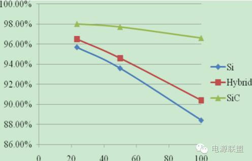
Figure 2 Efficiency distribution of different devices at different frequencies
It can be seen from Fig. 2 that for the all-Si device, as the switching frequency increases, the switching loss increases a lot and the efficiency decreases more. For the lower switching frequency of 23.4 kHz, the efficiency of the all-Si device inverter and the full SiC device inverter is not much different, only 1.8%, but when the switching frequency is increased to 100 kHz, the efficiency difference is large, and the inverse of the full SiC device The converter efficiency can be 8% higher than that of an all-Si device inverter.
3.2 Application of SiC device in transformer rectifier
In a power supply system where the main power source is an AC power source, a DC secondary power source is indispensable for supplying power to DC equipment such as radio communications, radar, flight driving equipment, control and protection devices, relays, signal devices, and motors.
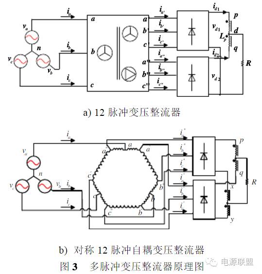
The transformer rectifier is a converter with a large output power on the aircraft, and therefore, in addition to requiring a small volumetric weight, it must have high efficiency. The transformer rectifier can be divided into a Transformer Rectifier Unit (TRU) and an Auto Transformer Rectifier Unit (ATRU) according to the type of transformer in the rectifier. Multi-pulse rectifiers have been used extensively in the B787 and A380. For example, the practical multi-pulse transformer rectifier in the B787 power system is mainly used to rectify the AC bus voltage to 28V low-voltage DC output, and supply power to DC fuel pump, igniter, flight deck display and other load devices; and multi-pulse auto-coupled transformer rectifier The AC bus voltage is rectified to 270V high-voltage DC output for use in hydraulic electric pumps, nitrogen generator systems, ring-controlled compressors, and engine start-up load devices. Figure 3 is a block diagram of a multi-pulse transformer rectifier.
As can be seen from FIG. 3, the transformer rectifier includes a main transformer that converts an alternating current voltage into a required voltage, and a rectifying circuit that converts alternating current electric energy into direct current electric energy. Since the main component of the rectifier circuit is a diode, the voltage stress is the maximum value of the input line voltage of the rectifier bridge. For a multi-pulse transformer rectifier, a diode with a withstand voltage of several tens of volts and a current rating of several tens to several hundreds of amps is generally selected. Therefore, ordinary Si diodes can meet the requirements; for multi-pulse autotransformer transformers, a fast recovery diode with a withstand voltage of 600V and a current rating of tens to hundreds of amps is generally used, and there is a problem of reverse recovery, and the conventional The Si diode can't withstand high temperature, and the SiC Schottky diode has almost no reverse recovery current, which can reduce the switching loss of the device, and the SiC Schottky diode can withstand high temperature and can reduce the heat dissipation pressure, which is more suitable for aviation systems. High temperature requirements.
3.3 Application of SiC Devices in Straight Converters
Straight converters are widely used on aircraft. The internal power supply of constant speed constant frequency power supply (CSCF) and variable speed constant frequency power supply (VSCF) controller GCU adopts common buck and buck/boost switching power supply. The input voltage of the converter is permanent. The DC voltage after rectification and filtering of the magnetic auxiliary exciter outputs voltages of different sizes and positive and negative polarities for use in templates of different functions in the GCU. There are two types of input voltages for the internal power supply of avionics. One is low-voltage direct current, the rated voltage is 28VDC, and the other is alternating current, (single-phase voltage is 115VAC, three-phase is 115/200VAC) or high-voltage DC voltage is 270VDC. There are also two types of output voltages, low voltage and high voltage. The latter are mainly used in communications, radar, electronic countermeasure equipment transmitters and various cathode ray tube displays, with voltages ranging from tens of thousands of volts to tens of thousands of volts; low voltage outputs of 24 VDC and ±12 VDC. , ±5VDC, +6.3VDC, +3.3VDC, etc. When the input is low voltage and the output is also low voltage, most power modules are used. Where the input is high voltage and the output is high or low voltage, most of the isolated straight converters are used.
Figure 4 is a non-isolated buck circuit diagram using SiC-MOSFET. When Si fast recovery diode and SiC Schottky diode are used as freewheeling tubes respectively, the temperature of the heat sink of the MOSFET and freewheeling diode is measured. 5 is shown. The measurement results reflect the use of a SiC Schottky diode as a freewheeling diode to lower the temperature rise. This is mainly due to the fact that SiC Schottky diodes can significantly reduce system losses, resulting in lower temperatures for MOSFETs and freewheeling diodes.
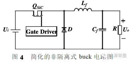
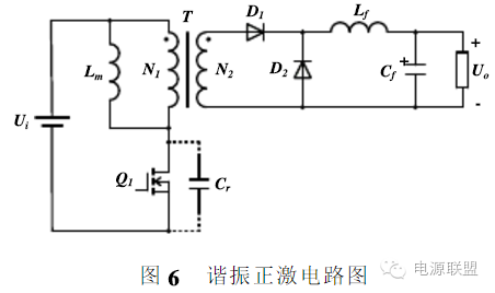
Figure 6 is a resonant forward circuit diagram. When the input voltage is 270VDC and the output voltage is 28VDC, the selection of the primary side power tube must take into account the relationship between the maximum blocking voltage and the resonant peak. It is assumed that the peak value of the resonant voltage is 800V, considering safety. For the margin, a power tube with a maximum blocking voltage of 1200V is required. Under this quota, the Si-MOSFET has a large on-resistance, and the Si-IGBT has a current tailing problem, which limits the switching frequency. SiC-MOSFETs have both low on-resistance and high frequency operation, which is suitable for use. The theoretical maximum voltage of the secondary rectifier diode is about 200V, and the theoretical maximum voltage of the freewheeling diode is 85V. Therefore, the two need to use different diodes, the rectifier tube selects 400V/40A, and the freewheeling tube selects 200V/20A. At this time, if a common Si diode is used, the reverse recovery time is generally several tens of nanoseconds, which will affect the efficiency of the whole machine and increase the heat generation. If it is replaced by a SiC Schottky diode, the system temperature can be lowered and the efficiency can be lowered. improve.
3.4 Application of SiC Devices in Motor Drivers
At present, the flight control actuators, oil pump motors and environmental control systems in aviation systems require motor drives. The power requirements of these motors are increasing. However, due to the limitation of the battery voltage on the aviation system, only the boost current can output sufficient power. The large current brings more power dissipation and heat generation, which increases the size and weight of the drive, which inevitably increases the invalid load of the entire system of the aeronautical equipment and shortens the stroke.
The high temperature resistance and reverse recovery current of the SiC Schottky diodes can greatly improve the performance of the motor driver, reduce the power dissipation, volume and weight, and improve the reliability of the product.
In addition, when the SiC MOSFET fabrication process is mature, if it can replace the currently used switching power device, its high temperature performance can further reduce the size and weight of the motor driver. Figure 7 is a schematic diagram showing the principle of connecting a three-phase inverter to a motor.
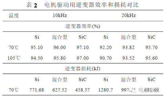
Table 2 shows the motor driver for the oil-water separator US06. The efficiency and loss at different temperatures of 10 kHz and 20 kHz are used for the three different device combinations of the full Si device, the hybrid device, and the full SiC device. Compared.
Since AC power cord is output of high voltage electric power, there is a risk of electric shock injury, therefore, All the AC power cord must comply with safety standard to produce. AC (Alternating Current) Power cord is to transmit high voltage. It is used to drive machinery or home appliances.
AC Power cord,power cable, batter cable, power cord
ETOP WIREHARNESS LIMITED , https://www.wireharness-assembling.com