Abstract: According to the requirements of battery rated constant current charging, a design scheme of a new battery constant current charging power supply based on DSP and variable parameter integral separation PI control is presented. The system structure, working principle, control strategy and software design of the power supply are introduced. The power supply is currently in use.
1 Introduction
When the battery is normally charged, the better charging method is the grading and sizing method, that is, using a large constant current at the initial stage of charging, charging for a certain period of time or after the battery reaches a certain voltage, switching to a smaller constant current charging. At the same time, the battery constant current charging power source is different from the ordinary DC power source, and its working load range is very wide, and its output voltage may change from approximately zero to the rated value. Therefore, the smooth transition of the battery charging phase is ensured in a wide load range, and the constant current characteristic at different stages is a design difficulty of the battery constant current charging power supply. The two-stage constant current charging power supply based on DSP variable parameter integral separation PI adjustment designed here can easily solve this problem.
2 system structure and working principle
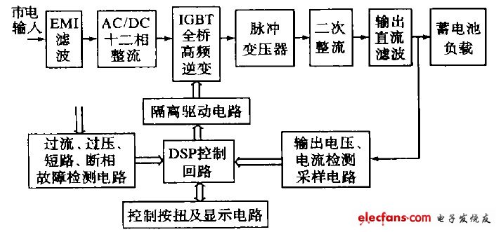
Figure 1 shows a block diagram of a battery constant current charging power supply. The power supply can perform two-stage constant current charging on the battery. The two-stage charging termination condition can be divided into charging time principle, charging voltage principle or time/voltage mixing principle, and can automatically complete two-stage current conversion, charging principle conversion and corresponding charging. Adjustment of parameter values.
The working principle of the main circuit of the device is to first perform EMI filtering on the 380 V input AC mains, and convert the AC power into DC power by using an uncontrolled rectifier circuit with a 12-phase autotransformer, thereby effectively reducing the input stage AC/DC conversion. The harmonic content increases the power factor and reduces the capacity of the input transformer. The full-bridge high-frequency inverter circuit is used to invert the direct current into a high-frequency bipolar PWM wave, which is stepped down by the high-frequency pulse transformer, double-wave rectified and output filtered, and finally outputs a constant direct current to charge the battery load.

Figure 1 Block diagram of constant current charging device
The control system consists of DSP and its peripheral circuits, mainly to detect, sample and calculate the output voltage and current signals; receive and process external control commands; control the constant current charging; generate the driving signals; display data The function of sending and controlling the whole machine. The DSP control chip adopts the digital signal processor TMS320F240 produced by TI Company of the United States, which has a rich on-chip integrated peripheral, which greatly reduces the peripheral components of the DSP. In addition, its high-speed signal processing and digital control make it ideal for control systems that require complex algorithms.
3 control strategy
PI controller is widely used in the field of control because of its simple structure and high steady-state control. The mathematical model of the traditional digital PI regulator is:

Its increment expression is:
![]()
Where e ( k) , e ( k - 1) --- charging current k and k - 1 sampling error values
Kp ---proportional coefficient
KI --- integral coefficient
The traditional PI-adjusted Kp and KI are constant in the control process, while the device in the paper needs to perform hierarchical constant-current charging on the battery. The two-stage charging parameter values ​​are different and the load range is wide, so in order to achieve better control effect, According to the actual situation, the control parameters are adjusted accordingly. In different input quantity areas, the requirements for selecting PI parameters are different, and the value rules are:
The 1Kp value is large, the system response is fast, and the adjustment precision is high; but when the Kp value is too large, the system is overshooted or even unstable. Therefore, when the error e ( k ) tends to increase, it is necessary to appropriately reduce the Kp value to prevent overshoot; when the error e ( k) tends to decrease, the Kp value is increased to increase the system response speed.
The role of 2KI is mainly to eliminate the steady-state error to improve the adjustment accuracy of the system. The KI value is large and the error elimination ability is strong, but the phenomenon of integral saturation and adjustment of overshoot is likely to occur during the starting process.
To this end, KI is required to be zero when the error is large to eliminate the integral saturation phenomenon; when entering the steady-state region, the integral adjustment is added. This not only ensures the integral requirement in steady state, but also avoids the integral saturation phenomenon.
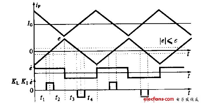
According to the above control rule of variable parameter PI, the system adopts a PI algorithm combining variable parameters and integral separation to adjust the driving pulse width of the inverter bridge. Figure 2 shows the control schematic. Where IG and IF are the given charging current value and the actual charging current feedback value, respectively. The control idea is to divide the fluctuation of the feedback current into four intervals according to the positive, negative and rising and falling trends of the charging current error e ( k), that is, interval 1 (0~ t1) and interval 2 ( t1~ t2 ), interval 3 (t 2~t3), interval 4 (t3~ t4). Different PI parameters are called in different intervals to achieve optimal PI adjustment. On this basis, the integral separation PI control algorithm is introduced, which not only maintains the integral action, but also reduces the overshoot, which greatly improves the control performance.

Figure 2 PI adjustment schematic
The specific implementation is as follows: 1 According to the actual situation of the system, a threshold ε ′ 0 is artificially set.
2 When │e ( k) │ ε ε, that is, when the deviation value e ( k) is relatively large, the integral link is removed, which can avoid excessive overshoot and make the system have a faster response.
3 When │e ( k) │ ≤ ε, that is, when the deviation value e ( k) enters the steady-state region, the integral link is added to ensure the control precision of the system.
4 In interval 1 and interval 3, the system output is approached to the given value IG by the regulator. In order to reduce the system steady-state error and improve the control accuracy, the large-scale adjustment coefficient KP1 is used to make the feedback current i F quickly approach I G. However, the increase of KP1 will reduce the relative stability of the system and even cause system instability, so in the interval 2 and interval 4 use a small proportional adjustment factor KP2 to reduce the speed at which the current feedback value deviates from the given value.
Through the above theoretical analysis, the mathematical expression of the control quantity Δu ( k) is:

In the formula ε---integral threshold.
e·( k) --- The amount of change in error, e·( k) = e ( k) - e ( k - 1).

Figure 3 Control system principle block diagram
Figure 3 shows a block diagram of the control system. Current A/D sampling synchronized with the T1PINT period of the DSP, and the average value of the measured current is used as the feedback value IF for the operation of the current regulator. After the integral parameter separation PI calculation of the variable parameter, the driving signal for driving the switching tube in the high frequency inverter circuit is adjusted, so that the adjustment charging current is kept constant.
Mtu Generator Set,Diesel Power Generator,Diesel Engine Generator,Silent Diesel Generator
Yangzhou Hengyuan Electromechanical Equipment Co., Ltd. , https://www.lchygeneratorset.com