1 Introduction
The circuit breaker plays an important role in cutting off the fault current in the power system. The large-scale application of the circuit breaker of sulfur hexafluoride (SF6) gas as the insulating medium in the power system greatly improves the operational reliability of the power system. However, due to the harsh operating environment and the change of running time, the SF6 circuit breaker inevitably has the problem of deterioration of insulation performance with partial discharge as the main feature. On-line monitoring of partial discharge of circuit breakers is an important technical guarantee. The ultra-high frequency (UHF) method that has emerged in recent years has been widely used in partial discharge monitoring due to its strong anti-interference ability and high sensitivity. Many European countries such as the United Kingdom and Germany have adopted UHF to detect partial discharge. In the newly revised IEC60270 and IEC605l7 standards in 2000, this method has been used as the main method for PD and GIS equipment. one. Based on the partial discharge monitoring system of electrical equipment based on ultra-high frequency method, the on-site live monitoring of SF6 circuit breaker is carried out, and the data analysis management software is developed by DELPHI and SQLserver2000, which realizes the effective management of partial discharge data.
2. Partial discharge characteristics of electrical equipment
The spectral characteristics of the electromagnetic waves generated by partial discharge are related to the geometry of the discharge source and the insulation strength of the discharge gap. The pulse current waveform generated by SF6 gas or insulating oil has a pulse steepness of nanosecond order, and the pulse duration is also between 1 ns and 100 ns, so that a large number of ultra-high frequency electromagnetic wave signals having a frequency above 300 MHz can be generated.
The UHF detection technology is to receive ultra-high frequency (UHF) electromagnetic pulse signals generated by partial discharge in a wide frequency band of 300 MHz to 1500 MHz. Since the UHF signal propagates quickly, the UHF electromagnetic interference signal outside the device under test (such as corona discharge in air) is not only narrower than the partial discharge signal inside the device, but its intensity also decreases rapidly with increasing frequency. The UHF component near or inside the device under test is relatively small, so that most of the air discharge pulse interference can be avoided.
3. UHF partial discharge test system
The computer is connected to the oscilloscope GPIB interface, and can receive the collected data according to the communication protocol, and further comprehensively analyze and manage. The functional block diagram of the software system is shown in Figure 2.
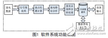
The entire system can be divided into two parts:
(1) Data comprehensive analysis function: including data pre-processing, discharge position determination, discharge feature extraction and discharge result analysis.
(2) Data management function: including analysis result storage, modification, query and deletion, etc., and data (including images) can be output in the form of reports and Excel, and the path of the output file is set by the user.
The system is built under the Chinese Windows operating platform, the human-computer interaction interface is friendly, the main program uses Delphi visual programming, and the background relational database selects SQ LServer2000.
4. Partial discharge test and analysis management of circuit breaker
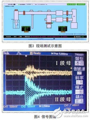
4.1 Field test test
The test was carried out on site, as shown in Figure 2:

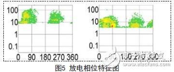
4.2 Characteristics of partial discharge
During the test, it was found that the measured signal spectra were basically the same and had the following characteristics:
After the initial determination of the discharge signal by the operating oscilloscope, the GPIB communication card communicates after the test is completed, and is actively transmitted to the computer, and the computer software further processes and manages the data.
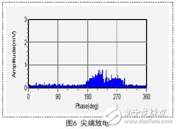
4.3 Discharge type analysis
Ultra-high frequency test found that there is obvious discharge signal. It is found by software processing that the maximum amplitude is 2.27mV, and the discharge signal is about 2308pC. The discharge is obviously distributed in the 1st and 3rd quadrants. The 3 quadrant data is obviously larger, and the analysis is considered to be the tip discharge. . As shown in Figure 5 and Figure 6.
Touch Screen,Outdoor Touch Screen,Capactive-Touch,Multiple Points Touch
Shenzhen Risingstar Outdoor High Light LCD Co., Ltd , https://www.risingstarlcd.com