This section shows how to build a basic NIOS II processor system that supports the RT-Thread operating system in Qsys, and build on this basis an example of creating two static threads with LED blinking. RT-Thread operating system version: 3.0 software version: Quartus II 13.0 development environment: Windows7 64-bit flagship hardware platform: Xiaomeige AC620 FPGA development board embedded processor: NIOS II

Build a NIOS II CPU system that supports the RT-Thread operating system
Built in Qsys to support the RT-Thread operating system NIOS II processor system, in addition to the necessary NIOS II processor, RAM memory (on-chip RAM, SRAM, SDRAM, DDR2), FLASH memory (EPCS), in order to support RT- The operation of the Thread operating system also requires the addition of UART serial peripherals, timer peripherals, and the addition of a PLL phase-locked loop in order to enable the system to operate at higher frequencies. At the same time, in order to be able to drive the LED lamp, it is also necessary to add a positioning wide output type PIO according to the actual hardware condition to drive the LED lamp. This system mainly includes the following peripherals:
The PLL clock management unit outputs two clocks with a phase difference of 90°, one for all logic in the system, and one for the clk pin of the SDRAM chip. (phase is -90°)
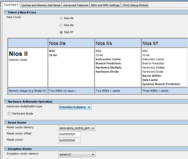
NIOS II processor, select f (fast) version, other defaults.
SDRAM controller, 16-bit data bit width, 12-bit row address, 9-bit column address, used as data and instruction memory for NIOS II
EPCS controller for power-down storage of hardware and software firmware information for FPGA and NIOS II
UART (RS232) controller, used as a system standard input and output device, default 115200 baud rate
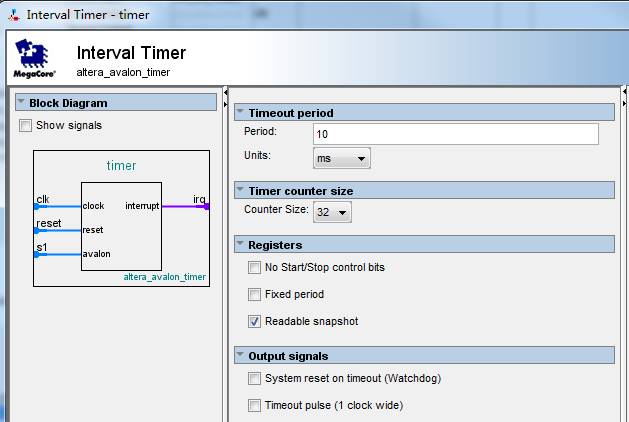
The Timer timer sets the default 10 millisecond timer and can be modified by software to modify the timing.
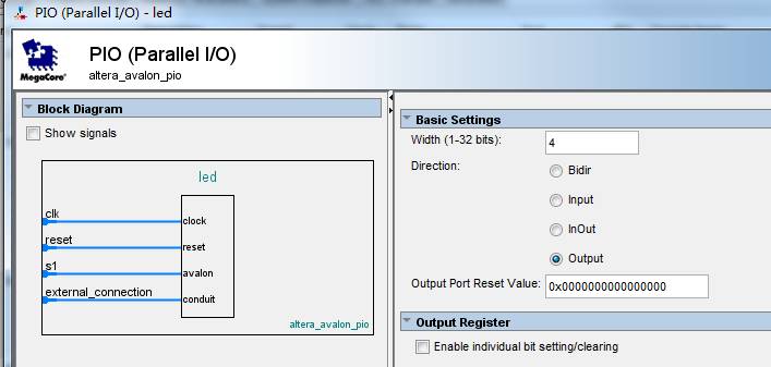
PIO, output type PIO only, 4 bits, corresponding to 4 LED lights on the development board
The following picture shows the minimum NIOS II application system built.
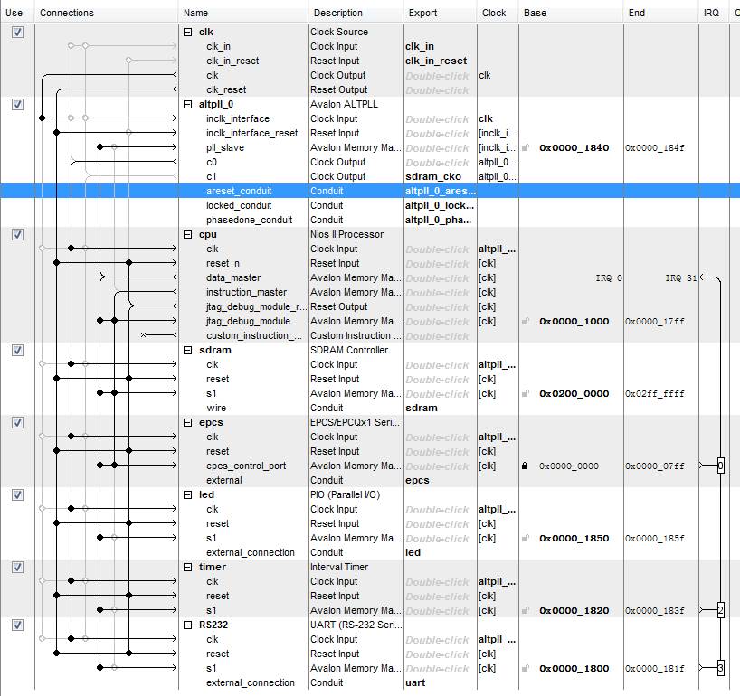
It should be noted that the PIO for driving the LED is 4 bits, and is directly named for LED. The uart serial port is named RS232, which is to correspond to the relevant code in the BSP file of the NIOS II officially provided by RT-Thread.
NIOS II CPU related settings
Timer parameter setting
UART controller related settings

LED PIO related settings
Instantiate a CPU system in a Quartus II project
Design top level file
Name the system built in Qsys as mysystem, then generate the HDL file, add the mysystem.qsys file to the Quartus II software, create a new Verilog file, and improve the top-level instantiation information. The improved code is as follows:
module ac620_ghrd (input wire reset_n, input wire clk, output wire [11: 0] sdram_addr, output wire [1: 0] sdram_ba, output wire sdram_cas_n, output wire sdram_cke, output wire sdram_clk, output wire sdram_cs_n, inout wire [15: 0] sdram_dq, output wire [1: 0] sdram_dqm, output wire sdram_ras_n, output wire sdram_we_n, output wire [3: 0] led, input wire uart_rxd, output wire uart_txd, output wire epcs_dclk, output wire epcs_sce, output wire epcs_sdo, input wire epcs_data0); mysystem u0 (.clk_in_reset_reset_n (reset_n), .clk_in_clk (clk), .sdram_addr (sdram_addr), .sdram_ba (sdram_ba), .sdram_cas_n (sdram_cas_n), .sdram_cke (sdram_cke), .sdram_cs_n (sdram_cs_n), .sdram_dq (sdram_dq), .sdram_dqm (sdram_dqm), .sdram_ras_n (sdram_ras_n), .sdram_we_n (sdram_we_n), .led_export (led), .uart_rxd (uart_rxd), .uart_txd (uart_txd), .sdram_cko_clk (sdram_clk), .epcs_dclk (epcs_dclk), .epcs_sce (epcs_sce), .epcs_sdo (epcs_sdo), .epcs_data0 (epcs_data0), .altpll_0_phasedone_conduit_export (), .altpll_0_l Nocked_conduit_export (), .altpll_0_areset_conduit_export () ); endmodule
Set EPCS pin function
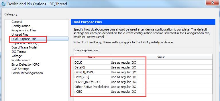
According to the pin assignment table of the AC620 FPGA development board or the silkscreen on the back of the development board, the correct pin is assigned one by one. Note that all IO levels are set to 3.3LVTTL to prevent the SDRAM memory from being driven properly. In addition, due to the use of EPCS, you need to set its function to regular IO in Quartus, as shown below:
Add an SDC constraint file
When doing NIOS II-based SOPC development, it is important to add SDC constraint files to constrain the system clock to ensure that the Quartus II software can lay out the system according to the frequency requirements of the operation. Otherwise, without constraints. The entire system may have a maximum operating frequency lower than 50MHz, and there will be various failures such as the system failing to operate normally and the software cannot be downloaded. The constraint file in this example is relatively simple. You only need to save a new sdc file and add it to the Quartus II project.
set_time_format -unit ns -decimal_places 3 create_clock -name {clk} -period 20.000 -waveform {0.000 10.000} [get_ports {clk}] derive_pll_clocks
After the addition is complete, compile the entire project and get the sof file.
Create a NIOS II application engineering template
Open the Quartus II integrated NIOS II software development tool (based on Eclipse) and switch workspaces to the Quartus II project directory.
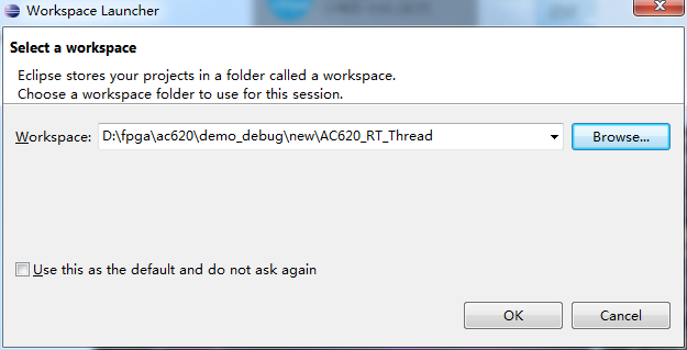
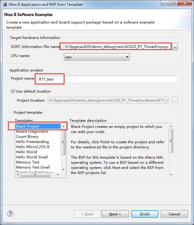
Then create a new blank template project and bsp project as shown below. Note that the sopcinfo file path must not be wrong.
Porting RT-Thread operating system
Download RT-Thread operating system source code
Download the source file of the RT-Thread operating system from git, source code: https://github.com/RT-Thread/rt-thread select the master branch, click the Clone or download button, select Download zip to download the source file, of course This file can also be obtained from the zip file of this example we provided.
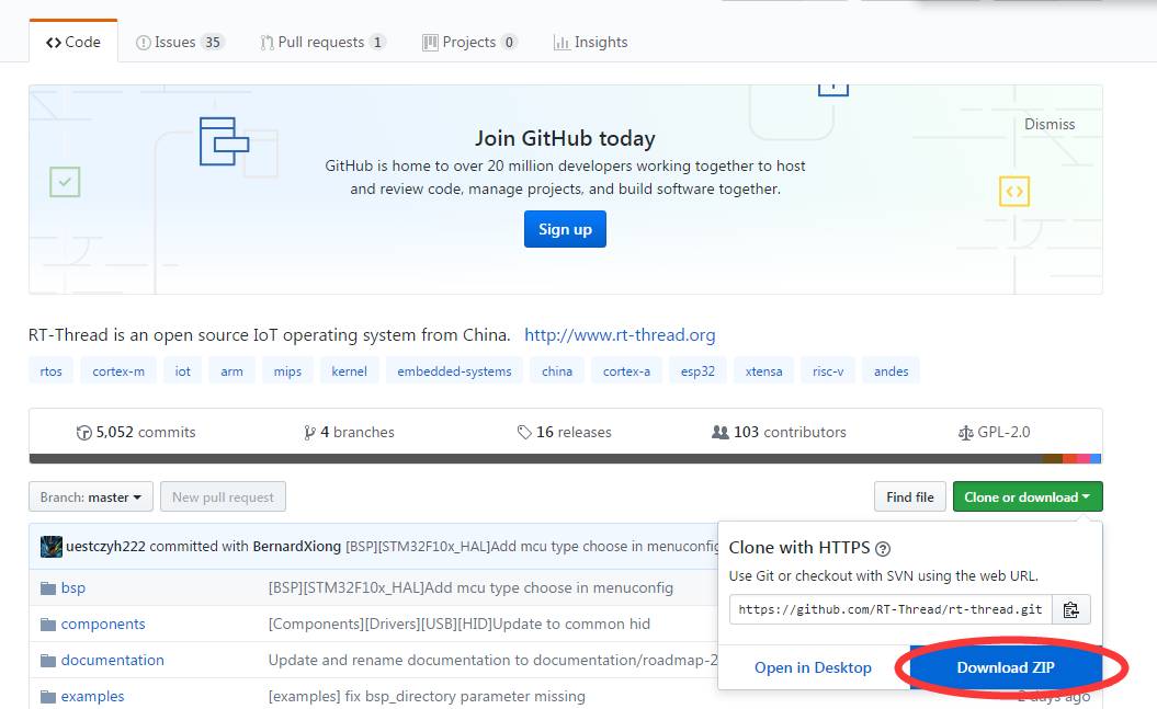
The file name after the download is complete: rt-thread-master.zip
Porting RT-Thread operating system source code
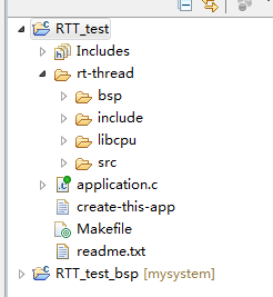
Create a new folder under the RTT_Test project, name it "rt-thread", add the src folder, include the folder to the rt-thread folder, and then add the nios part of libcpu to the rt-thread folder. Note that libcpu provides support for CPUs of various architectures. We only need the nios part here, and other parts do not need to be added to the project. The above completes the addition of the RT-Thread operating system source code. But this time is not complete, we also need to add the bsp file to the NIOS II CPU. This file is in the nios ii path under the bsp path. We copy all the .c and .h files in the path to the project. , application.c is the application part of the whole system, that is, the file where the main function is located, so the file is removed from the rt-thread folder to the root directory of the software project (drag and drop), and the completed project is as follows Show (for details, please refer to the example project file we provide).
Set the header file search path
After adding all the files, we must also add the header search path to the software settings, select the RTT_test project, right-click and select the Properties option, select the Nios II Application Paths option in the pop-up dialog box, add include and bsp In the folder path header file path, then confirm the shutdown. If the following relative path transition prompt pops up, select Yes.

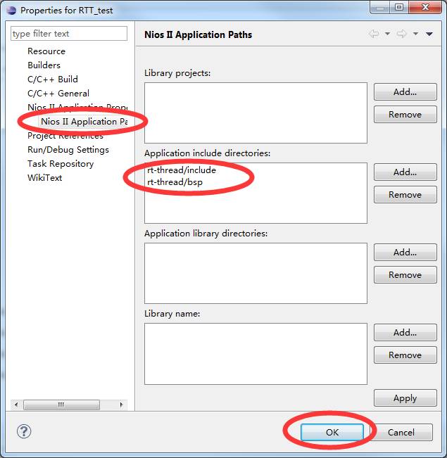
At this point, all the requirements for running the RT-Thread operating system have been met.
Turn off FINSH support
Next, we open the project's rt-thread -> bsp -> rtconfig.h file, locate the line 80 or so, and add the #define RT_USING_FINSH sentence with a single-line comment "//" to block the definition. That is, the FINSH function is not used.
Run RT-Thread operating system
Compile and run the program
Then fully compile the entire project (shortcut key Ctrl + B), compile without errors, you will get the elf file that can be downloaded to the NIOS II CPU, then click RUN -> Run Configurations option in the menu bar to open the download Run the page.

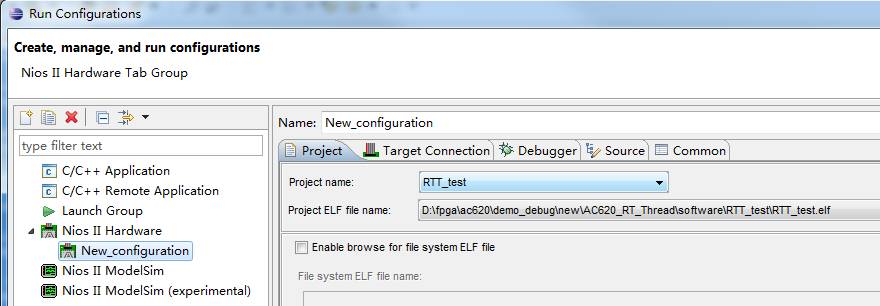
Create a new hardware run configuration and select the RTT_test project, then switch to the Target Connection tab and refresh the connection to confirm that the hardware USB Blaster has found the CPU. Note that before this operation, you need to download the sof file generated by the Quartus II software compilation to the development board, and use the Micro USB cable to connect the development board and the computer, and open the serial debugging tool to find the corresponding serial port of the development board, set the wave. Rate 115200, ASCII reception.
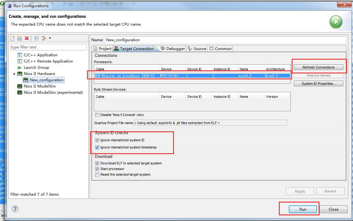
Check the Ignore system id and timestamp option and click Run. You can start the download of the software program.
Experimental result
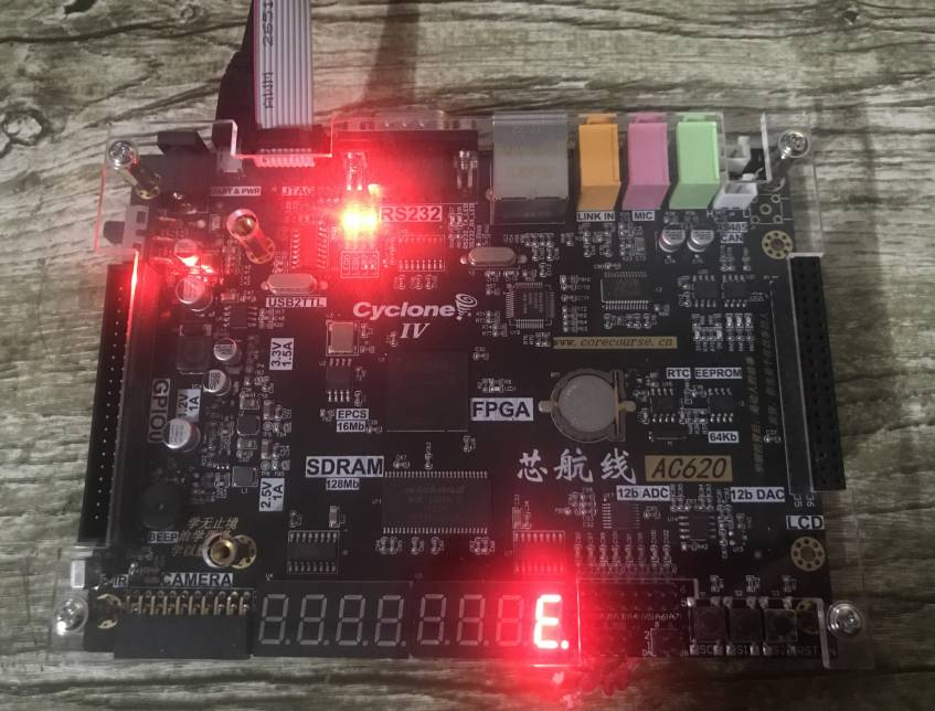
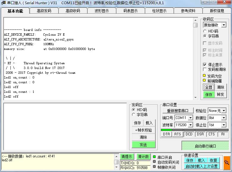
After the download is complete, you can see the information printed when the system is running on the serial debugging assistant. At the same time, the four LED lights on the development board cycle flash.
12V100Ah Lithium Ion Battery,Deep Cycle Solar Battery,2V 100Ah Lifepo4 Battery,12V 100Ah Lifepo4 Battery Pack
Jiangsu Zhitai New Energy Technology Co.,Ltd , https://www.zhitainewenergy.com