Improved differential amplifier circuit
In the differential amplifier circuit, increasing the resistance of the emitter resistance Re can improve the common mode rejection ratio. However, it is not easy to make large-resistance resistors in integrated circuits; the use of high-resistance Re requires a high-regulated power supply, which is not suitable. If the quiescent current of the emitter of the transistor is 0.5mA, the current in Re is 1mA. When Re is 10kΩ, the value of the power supply VEE is 10.7V. Under the same quiescent operating current, if Re = 100kΩ, the value of VEE is about 100V. 
In order to use both a lower power supply voltage and a large equivalent resistance Re, a constant current source circuit can be used instead of Re. When the transistor works in the amplifying area, its collector current is almost determined by the base current and has nothing to do with the tube voltage drop. When the base current is a constant DC current, the collector current is a constant current. Therefore, to replace Re with an operating point stabilization circuit, the circuit shown in the upper right diagram must be used.
The constant current source circuit not only sets a suitable quiescent operating current for the differential amplifier circuit at a low power supply voltage, but also greatly enhances the common mode negative feedback effect, so that the circuit has a stronger ability to suppress common mode signals.
As shown in the upper right figure, the constant current source circuit can be replaced with a constant current source. In the actual circuit, a potentiometer with a very small resistance is usually added between the emitters of the two tubes, see Rw in the figure below.
Zero-adjusting potentiometer Rw: adjust the sliding end position of the potentiometer to make the circuit when uI1 = uI2 = 0, uO = 0, Rw is called zero-adjusting potentiometer. 

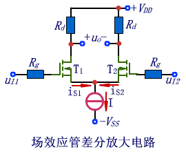
In order to obtain a differential amplifier circuit with high input resistance, the transistor can be replaced with a field effect transistor, as shown in the upper right figure. This type of circuit is particularly suitable as an input stage for directly coupled multi-stage amplifier circuits. Generally, the input resistance can be regarded as infinite. Its application is the same as the transistor differential amplifier circuit.
APM ac power source model SP300VAC1500W provides a complete AC test solution with built in arbitrary waveform generator to simulate many types of power waveforms, at power levels up to 1500 VA.With better accuracy and faster response time, The dc and ac output power supply offers greater advantage for R&D and compliance tests.The application is from bench-top testing to mass production.
This AC source model SP300VAC1000W adopts high speed DSP+CPLD control, high frequency PWM power technology and active PFC design to realize AC/DC stable output.
Some features as below:
- 4.3"large touch color screen
- AC+DC mixed or independent output mode
- Capable of setting output slope/phase angle
- Built-in IEC standard test function
- Built-in multiple protections
- Built-in power meter
- Support impedance function
- Support for LIST/PULSE/STEP mode & Transient mode
- Standard RS232/RS485/USB, Optional GPIB//LAN
- Support harmonics/inter-harmonics simulation and measuring function
- Support for USB data import/export and scree nap from front panel
1500W AC Power Supply,Adjustable 1500W Power Supply,1500W Power Supply,Ac Dc Power Source
APM Technologies Ltd , https://www.apmpowersupply.com