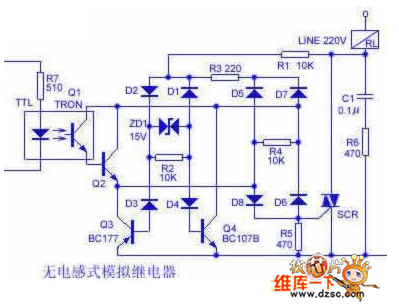
In the lower electrical diagram, the 220V power supply is biased by the load RL, R1, D1~D4, ZD1 for Q4 and Q3 in the positive and negative half cycles; and the power supply is provided by the optical coupler Q1 via R3 and D5~D8. When the current level TTL circuit outputs a high level signal, the photocoupler is turned on during the positive half cycle of the mains, so a voltage drop is generated across R5, triggering the SCR to conduct, and the load RL is energized. The entire circuit functions like a relay, but does not generate a reverse induced voltage, which avoids the possibility of damage to the load caused by high back pressure breakdown. C1 and R6 are pulse absorbing elements, and R3 acts as a current limiting.

Inductive analog relay diagram
To avoid the RL being an inductive load, the voltage of the thyristor and the 90° phase generated by the optocoupler power supply, the power supply of the optocoupler in the circuit is taken from the anode of the SCR and not directly from the mains supply.
118 size switch socket, wall switch socket, freedom switch socket
Guangdong Shunde Langzhi Trading CO., Ltd , https://www.langzhielectrical.com