1 Introduction
This article refers to the address: http://
Images are the most important source of information for humans. In the era of information explosion, image data compression technology is an important means to solve the storage and transmission of massive image data. Therefore, seeking the best image data compression technology has always been a research hotspot in the field of information technology.
With the development of medical imaging technology and computer technology, the application of digital medical images in medical clinical diagnosis and teaching research is increasingly widespread. On the one hand, the emergence and development of X-ray, computed tomography (CT) to nuclear magnetic resonance (MRI), ultrasound images, etc., make the quality of medical images higher and higher, playing an increasingly important role in medical diagnosis; On the other hand, medical images have an increasing amount of information. In hospitals using PACS systems and telemedicine diagnostic systems, a large amount of storage space is required for storage and transmission. The size of image data will directly affect the transmission. The speed that causes the destination clinician to fail to make an effective diagnosis. Medical image compression coding has become an important research direction of medical informatics. It requires that reconstructed images can not have obvious distortion, and can meet the increasingly large compression and transmission tasks of medical image data.
2. Introduction to spatial domain image compression algorithm
2.1 Defects in the frequency domain image compression algorithm
In recent years, the compression of image data has made great progress, and many excellent compression algorithms have emerged. The wavelet-based compression method, which is currently widely used and has been incorporated into the new international standard, is a mature compression method with high fidelity compression effect, but for medical image compression, this method has some serious drawbacks:
(1) The wavelet-based compression method replaces the compression ratio by sacrificing high-frequency information and preserving low-frequency information. The image is lost by high-frequency information after being decomposed by wavelet decomposition, and with the increase of compression ratio, high-frequency information The more severe the loss will be, which will directly result in the loss of texture details in the image;
(2) The method must be based on large-area images (the restored image quality will decrease sharply with the reduction of the base area used for wavelet decomposition), and the distortion-free coding can be performed on the basis of multiple two-dimensional wavelet decomposition. Get high-fidelity compression, but this algorithm based on large area is difficult to achieve real-time compression.
2.2 Introduction to spatial domain image compression algorithm
Because of the above defects in the transform domain coding, people have turned their attention to the spatial domain-based compression method.
In the literature [4], the author proposed a multi-resolution spatial resampling image compression algorithm RBC algorithm. The RBC algorithm has a compression quality not lower than the wavelet-based compression algorithm when the compression ratio is about 4 times. However, because the RBC algorithm is too simple in describing the structure of the image, the compression quality decreases rapidly with the increase of the compression ratio. Therefore, the literature [5] improves on this basis, and proposes an image compression algorithm based on the pattern feature. SDBC algorithm. The algorithm uses 4×4 pixel blocks as the basic image sub-area and is used as the basic unit of compression processing. Each image sub-area is divided into flat area, coarse texture area and fine texture area according to the complexity of its texture structure. Class, taking the average variance of the image in the sub-region as the criterion of classification, its compression quality is significantly improved compared with the RBC algorithm.
Although the SDBC algorithm considers the distribution of textures in the image and performs partition compression, the algorithm only uses 4×4 blocks, and only three classification modes are performed. Obviously, this method cannot cover all the textures in the image. . Therefore, this paper continues the algorithm idea of ​​SDBC, and draws on the intraframe coding technology in H.264 video coding standard, and proposes a compression method based on spatial prediction and transform to solve the above problems.
3. Medical image compression method based on spatial prediction and transformation
3.1 Overview of medical image compression methods based on spatial prediction and transformation
The image compression algorithm based on spatial domain generally can't perform full-image operations like the wavelet transform-based algorithm, but it needs to be block-processed. In order to facilitate computer processing, the block size of general images is 2n×2n. In this paper, 4×4 and 16×16 blocks of different sizes are selected as the processing window, and SAD is used as the criterion for selecting the window size. The algorithm encodes in units of 16×16 macroblocks.
The general flow of medical image compression based on spatial prediction and transformation is as follows:
(1) dividing the image into a plurality of 16×16 macroblocks;
(2) Predictive analysis: predictive analysis of a 16×16 window. After analysis, the window size of the final encoding is obtained: 16×16 or 4×4, and the best prediction mode;
(3) Predictive coding: The block is transformed, quantized, and scanned according to the window size and the best prediction mode obtained in (2). In addition, inverse transform and inverse quantization are performed to generate a reconstruction window.
(4) Entropy coding the data obtained in (3);
(5) Repeat (2), (3), (4) to traverse all 16×16 macroblocks in the image.
3.2 Forecast Type
According to the size of the window, the algorithm has two types of prediction, namely 4×4 prediction type and 16×16 prediction type. Figure 1 shows the pixel distribution for the 4×4 prediction type. In Figure 2, there are 8 prediction modes other than mode 2, and mode 2 is the mean prediction mode, which uses the upper and left sides of the current block. The mean of the gray values ​​of the pixels is taken as the predicted value for each pixel of the current block. There are four prediction modes for the 16×16 prediction type, which are vertical prediction mode, horizontal prediction mode, DC prediction mode and plane prediction mode (as shown in Figure 3). The 4×4 prediction type is suitable for image regions with multiple prediction details, relatively large transformations, and multiple different objects, and the 16×16 prediction type is more suitable for predicting smooth image regions, and encodes relatively invariant portions of the image.

Fig.1 Distribution of pixel points of 4×4 block prediction type
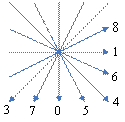
Figure 2 4 × 4 block prediction direction
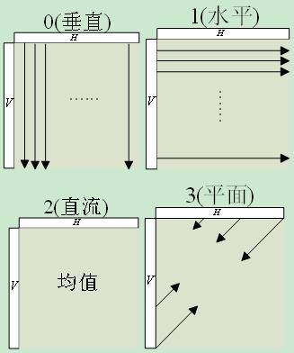
Figure 3 16 × 16 block prediction mode
The algorithm uses the absolute error and SAD (Sum of Absolute Difference) as the criterion for judging the coding window. The absolute error sum refers to the sum of the absolute values ​​of the differences between the block to be coded and the block to be predicted, that is, the sum of the residuals. Suppose the current block is represented by S(i,j), and the predicted value is pred(i,j),i,j=0,1,...,N, then ![]()
The smaller the SAD value is, the smaller the residual value of the image is, so that the closer the current block to be coded is to the prediction block, the higher the prediction accuracy of the corresponding prediction mode is. The larger the SAD value is, the more the residual value of the image is. Large, so that the prediction block does not respond well to the current block to be coded, and the prediction accuracy of the corresponding prediction mode is lower.
In order to comprehensively consider the different bias directionality of various prediction modes, when the macroblock is encoded, all prediction modes are traversed, and the optimal mode is selected as the final coding mode by means of the mode decision criterion.
3.3 transformation
Since the discrete cosine transform (DCT) is very close to the statistically optimal KL transform, DCT is typically used in transform coding of image blocks. However, DCT has a disadvantage: the partial coefficients in the DCT transform matrix are irrational numbers, and after the transform and inverse transform are performed on the computer by the iterative method, a consistent initial value cannot be obtained. In this paper, the idea of ​​H.264 intraframe coding is used, and the integer DCT [6] is used instead of the floating point number DCT. The integer DCT can obtain the frequency decomposition similar to DCT after acting on the image signal. At the same time, the purpose of the orthogonal transform is to reduce the correlation of the transform coefficients, so that the energy of the transform coefficients is concentrated on fewer components, and the energy before and after the transform. There is no loss, and integer DCT has the same effect as DCT in removing spatial correlation.
Two transformations are used in this paper: integer 4×4 DCT and 4×4 Hadamard transform.
Integer 4×4DCT transform reduces rounding error, reduces computational complexity, and improves computational accuracy; using 4×4 blocks for transform, the size of the transformed block is reduced, and blockiness can be reduced; at the same time, in order to make small size The transformation method does not produce gray-scale differences between blocks in a smooth area of ​​a large area in the image, further reduces the correlation between DC coefficients, and performs a second block transformation on the DC coefficients of 16 4×4 blocks, namely Hadamard. Transform.
4. Test analysis and conclusion
4.1 Comparison of compression performance
The CT image and the MRI image are compressed (the CT image and the MRI image are shown in FIG. 4 and FIG. 5 respectively), and the compression result of the algorithm provided by this paper is compared with the compression result of the JPEG2000 compression algorithm, and the objective evaluation index used is adopted. For the peak signal-to-noise ratio (PSNR), the results are shown in Figure 6 and Figure 7 (for the convenience of description, the algorithm provided in this paper is temporarily represented by NEW).
In order to compare the merits of the two algorithms, the format, size and bit depth used to test the image are represented by Table 1 below.
Table 1 Three image properties for comparison
| Test image | Image format | Image size | Bit depth |
| CT | RAW | 512×512 | 8 |
| MRI | RAW | 512×512 | 8 |
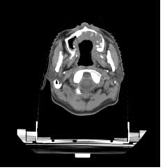
Figure 4 CT image 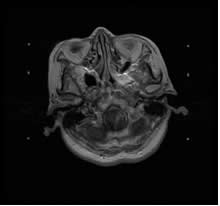
Figure 5 MRI image
The objective evaluation parameter peak signal-to-noise ratio (PSNR) is defined as follows:

Where: f(i,j) is the original image, g(i,j) is the restored image, and M×N is the width×height of the image.
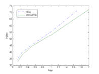
Figure 6 Comparison of peak signal to noise ratio curves of CT images
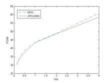
Figure 7 Comparison of peak signal-to-noise ratio curves of MRI images
4.2 Analysis of test results
For CT and MRI images, this paper provides a compression algorithm better than JPEG2000, in which the compression effect on CT images is significantly higher than JPEG2000.
5 Conclusion
Modern medical imaging equipment generates an ever-increasing amount of information, and its amount of information continues to increase. Therefore, studying medical image compression algorithms is of great significance.
In this paper, the shortcomings of wavelet domain compression algorithm based on frequency domain are discussed firstly. Then the image compression algorithm based on pattern feature is introduced briefly, and the idea of ​​the algorithm is continued. At the same time, the space coding based on H.264 is proposed. Image compression method for prediction and transformation. Finally, by comparing with the JPEG2000 compression algorithm and analyzing the test results, it can be seen that the method has better compression effect on CT images and MRI images.
With more than 15+ yrs rich MFG experience, you can definitely trust in and cooperate with.
Provide you with the supply of Personal Protective Equipment. to help you safely get back to your daily routine.
Our products include pulse Oximeter Finger, Forehead Thermometer, Automatic foam soap dispenser, etc.
Our strict quality control protocol thoroughly vets every aspect of production, storage, and shipments all the way way to our end customers.
infrared thermometers wholesale, forehead thermometer wholesale,wholesale thermometer suppliers
TOPNOTCH INTERNATIONAL GROUP LIMITED , https://www.micbluetooth.com