When using a multimeter, you should be familiar with the meaning of various symbols on the dashboard and the main functions of each knob and selector switch. Check whether the pointer points to the zero position. If not, you can adjust the mechanical zero position on the meter cover. Adjust the pointer to return to the zero position. Then according to the type and size of the measurement, turn the selector switch to the corresponding gear, and find the corresponding scale on the pointer dial.
Voltage and current measurement
Same as measuring voltage and current with a voltmeter and ammeter, when measuring voltage, a pointer multimeter should be connected in parallel in the circuit, and when measuring current, the multimeter should be connected in series in the circuit. In addition, when measuring DC voltage and current, you should also pay attention to the polarity of the test leads (the general rule is that black is negative and red is positive). What range may the maximum value be, or select the largest range of the meter, and then gradually reduce the range to obtain accurate readings. The range should be greater than the measured value, otherwise the meter may be damaged.
The actual value of the tested circuit is determined by this formula: actual value = pointer reading & TImes; range/full scale
In the formula: full scale is the maximum scale value on the selected scale. For example: use a pointer multimeter to measure the DC voltage, the range is 100V, the full scale is 50, and the pointer points to 20, then the actual value=20&TImes;100/20=40V.
Resistance measurement
Choose the appropriate magnification gear: When measuring resistance, select the magnification gear so that the pointer stays on the thinner part of the scale line. The closer the pointer is to the middle of the scale, the more accurate the reading; the further to the left, the more squeezed the scale line, the worse the accuracy of the reading. The magnification gear should be smaller than the measured value. Zero adjustment: Before measuring the resistance, you should touch the test probes together. The colleague turns the "zero adjustment knob" (the larger knob on the right edge of the multimeter as shown in the above right picture) so that the pointer just points to the zero position of the ohm scale , This step is called "zero adjustment" in the ohm range. This step must be repeated every time before changing the magnification gear to measure the resistance. This is an essential step to ensure accurate measurement. If the pointer cannot be adjusted in place, it means that the battery voltage is insufficient or there is a problem with the meter circuit. Cannot measure resistance with power: When measuring resistance, the multimeter is powered by a battery, and the measured resistance must never be charged, because the live measurement is equivalent to connecting an additional power source, which not only fails to obtain correct measurement data, but may also damage the meter head . The actual value of the measured resistance is derived from this: actual measured value = magnification & TImes; pointer reading. If the measured resistance reading is 25 on the 1000-fold gear, the measured resistance value is 25&TImes;1000=25000 ohms. Diode measurement
Everyone knows that generally there are diodes that directly indicate the positive and negative poles. When you see the white coil on the shell, it is the negative pole. Or the shorter side of the wire is negative. But what if there are no such features?
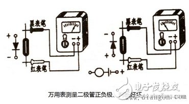
A multimeter is a tool that electricians have on hand. When using the ohm (resistance measurement) of the multimeter to measure the positive and negative resistance of the diode, because the multimeter is connected to the battery, pay attention to the terminals marked with "-" on the multimeter case. Connect the black test lead; connect the red test lead of the terminal marked "+" on the case. The current flows from the red test lead and flows back from the black test lead. In addition, the ohm file of Rx1000 should be selected for measurement, because the current of Rx1 file is too large, and the voltage of Rx10K file is too high, and it is easy to damage the diode, so it is not suitable for selection.

The specific test method is shown in the figure on the right. Connect the two test leads of the multimeter to the two pins of the diode respectively. The forward resistance of the diode is very small, generally tens of ohms to hundreds of ohms, and the reverse resistance is very large, generally between tens of kiloohms to hundreds of kiloohms. If in the two tests in the figure, the test on the right shows a small resistance and the test on the left shows a large resistance, it can be concluded that the pin connected to the red test lead on the right is the anode of the diode and the other pin is the cathode.
Some modern digital multimeters may have a gear for judging whether the diode is good or bad (on-off gear). Set the multimeter in this gear for measurement. If there is a reading, the red test lead is positive. If there is no reading or “1†is displayed, it is black. The test lead is positive.
Diode quality judgment
It is still the above measurement method using the resistance file of a multimeter to judge. If the measured forward and reverse resistance are very different, the measurement indicates that the unidirectional conductivity of the diode is good; if the resistance values ​​measured twice are very small or both are very large, it means that the diode has lost its unidirectional conductivity, and it is timely Bad diodes with quality problems.
1.27mm Ejector Header Connector
Shenzhen CGE Electronics Co.,Ltd , https://www.cgeconnector.com