Like most test tools, modern digital storage oscilloscopes (DSOs) have been evolving to meet the needs of designers and test engineers, striking a balance between performance, features, and practicality. However, its three basic characteristics—grid lines, cursors, and automatic measurement parameters remain the same, because for designers who are faced with increasing pressure to speed time to market, these characteristics are used correctly when applied. Has extremely important value.
This article will introduce how to properly use and use these basic characteristics of modern DSO, and provide practical definitions of measurement parameters for reference.
Three essential tools of modern DSOAn oscilloscope is a voltage response measurement instrument that includes three basic measurement tools. With the development of instruments, these tools continue to evolve. The earliest tool was the display grid or grid on the instrument display. The second tool introduced during the development of the oscilloscope is the cursor or marker. The third tool added last is to measure parameters. These parameters are increased with the introduction of digital oscilloscopes. These tools have not been replaced with the emergence of new technologies, which is enough to prove their practicality. Below we will introduce these three tools one by one to help you understand the reasons for using them and how to make the most of them.
Screen gridThe most primitive measurement technique is to use the grid lines on the screen and calculate the grid number. This method is mainly used to quickly estimate amplitude and time measurements. Displaying grid lines or grids is the first measurement tool that appears on an oscilloscope. The measurement method of the waveform is to record the number of grids covered by the waveform and then multiply it by the corresponding scale factor. On the Teledyne LeCroy HDO 4104A, we collected a waveform, showing a five-cycle sine wave (Figure 1), we can complete the measurement for this waveform.
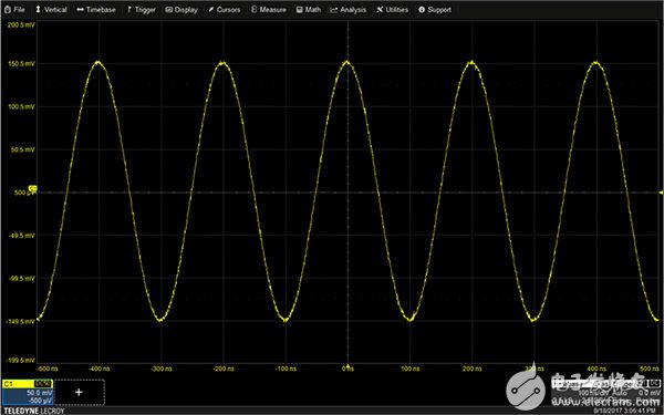
Figure 1: A typical oscilloscope display grid. The vertical scale factor read from the track descriptor of channel 1 (C1) is 50 millivolts (mV) per division, and the horizontal scale factor displayed in the time base descriptor is 100 ns per division. (Photo source: Digi-Key Electronics)
The sine wave trajectory covers six grids in the vertical direction, and multiplies the vertical scale factor of 50 millivolts (mV) per grid (see the channel 1 descriptor box) to calculate the sine wave amplitude of 300 mV (peak-to-peak value). Similarly, the period of the sine wave covers two horizontal grids, and each division in the time base descriptor box is 100 nanoseconds (ns), so the period is 200 ns. The method of calculating the number of lattices seems a bit primitive, but it is a very quick method for basic measurements. Most oscilloscope users can adapt to this method to verify the basic assumptions of the waveform to be measured and ensure that the oscilloscope is set up correctly.
cursorThe cursor is a display line that can be placed by the user, with associated amplitude and time readings. The cursor is placed on the point to be measured on the track. The cursor reading shows the amplitude, time, and the time difference between the cursor marking lines (Figure 2).
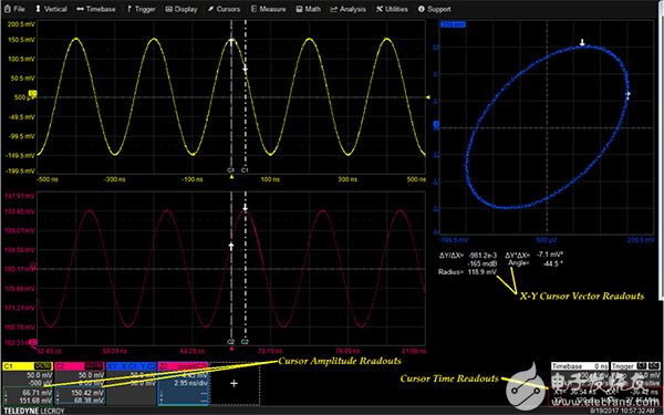
Figure 2: Trace and XY cursor showing cursor reading fields (including amplitude and time position) (Image source: Digi-Key Electronics)
The available cursor types include horizontal line, vertical line, and horizontal plus vertical line. The cursor types shown in the figure are vertical lines, including the horizontal and vertical readings of the points marked by the vertical cursor lines and arrows. The amplitude reading is displayed in the trace descriptor of each channel shown. The horizontal reading is below the time base and trigger descriptor grid. The horizontal reading shows the absolute cursor position relative to the trigger point, the time difference (Dt) between the cursors, and the reciprocal (frequency) of the time difference.
The cursor operation is extended to use on the XY display area. In addition to the normal amplitude and time readings of the cursor, users can also obtain vector angle (angle from downward arrow to upward arrow) and amplitude (radius from upward arrow to downward arrow) readings from the XY display area. These vector readings are displayed below the XY display area. The relative cursor on the XY display area can read the vector difference, including error vector amplitude (EVM) and phase angle.
The practical characteristics of the XY cursor are: the cursor position on the XY display area is tracked on the XT and YT components. Therefore, any abnormality on the XY display area can be tracked to the exact point on the component trajectory in real time.
Measurement parametersThe most accurate way to measure the waveform is to use the automatic measurement parameters provided by the oscilloscope (Figure 3).
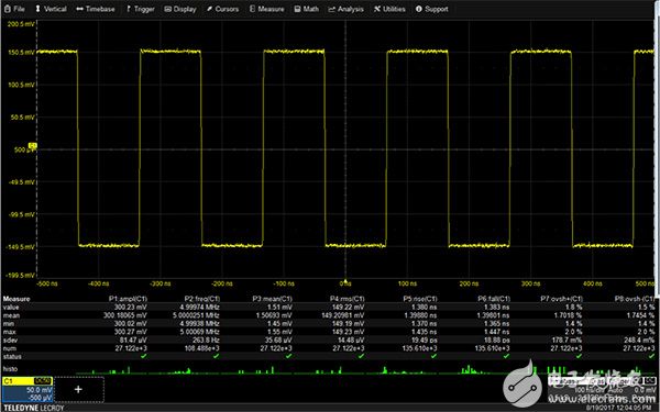
Figure 3: Teledyne LeCroy HDO 4104A oscilloscope measurement parameters showing up to eight parameter readings, including statistical data and "histogram". (Photo source: Digi-Key Electronics)
The Teledyne LeCroy 4104A and WaveSurfer 510 oscilloscopes provide more than 30 basic measurement values ​​and can display up to eight or six parameters at a time. WaveSurfer 3024 has 24 standard measurement values ​​and displays up to six parameters at a time. In specific analysis options, additional parameters are also provided.
The oscilloscope measures the timing parameters for each cycle of the displayed waveform. This function is called "full instance" measurement. The amplitude parameter accumulates a single value for each acquisition. The measurement table can display the latest value of each measurement parameter, or display the historical records of all measurements through parameter statistics. The figure above shows that parameter statistics is turned on. Available parameter statistics include average, minimum, maximum, and standard deviation. It also displays the total number of acquisitions (scans) included in the parameter statistics. It laid the foundation for statistical testing.
You can also open the histogram to show the distribution of measured values ​​for each parameter. Statistics and histograms help us understand the change of parameter values ​​in multiple measurements.
The trend function allows us to further understand the changes in measured values. The trend function can draw a graph of measured parameter values ​​in the order of measurement. The vertical axis unit matches the measurement unit, and the horizontal value is the measurement sequence number (Figure 4).
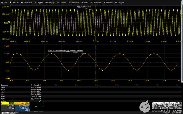
Figure 4: Example of an instantaneous frequency trend diagram of a frequency-modulated sine wave. The frequency is measured every cycle, and the drawing order of the median of the mathematical trace F1 follows the measurement order. (Photo source: Digi-Key Electronics)
The collected signal is a frequency-modulated sine wave; the signal frequency is measured on a cycle-by-cycle basis and drawn as a trend graph in the mathematical trace F1. The vertical axis of the trend graph is in hertz (Hz), while the horizontal axis is the measurement sequence number. The trend graph may have 20 to 1,000,000 points with a level of 1-2-5. These trend graphs are synchronized with the source trajectory, but the same number of points must be drawn.
Status icons, such as the green check mark below the statistics table, indicate the status of parameter calculations, including error conditions. If there is not enough data available, the reading is blank.
These measurements can set thresholds so that only data within the user-defined measurement thresholds are included in the measurement. This function is very useful in many applications, such as analyzing the data bus when the address and data signal waveforms share the same signal path. The measurement threshold can be set so that the measurement is performed only for the desired mode.
Pulse measurement is based on the IEEE 181 standard. The standard stipulates that pulse measurements must be statistically analyzed to minimize the impact of noise on pulse waveform measurements (Figure 5).
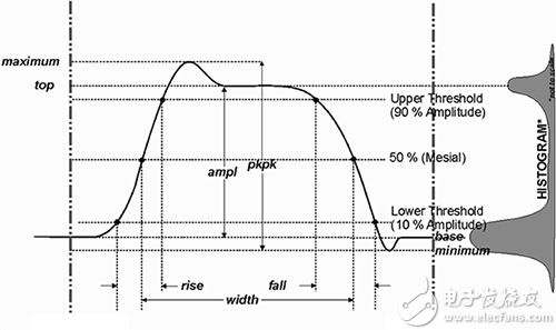
Figure 5: Example of IEEE 181 standard pulse measurement histogram. The pulse histogram will show two peaks. The average value of these peaks determines the peak and bottom values ​​of the pulse voltage, thereby minimizing the effects of noise. (Source: Teledyne LeCroy).
The IEEE standard specifies that a histogram of waveform samples should be drawn. The pulse histogram will have two peaks. The average value of the higher peak is the top of the pulse, and the average value of the lower peak is the bottom of the pulse. Using these averages can eliminate the effect of noise on determining the pulse amplitude. Therefore, the period, width, overshoot, rise time, and fall time can all be calculated more accurately.
If the histogram cannot display two different peaks, the oscilloscope will indicate that the waveform is not a pulse through the status icon, and the amplitude measurement is based on the maximum value minus the minimum value or peak-to-peak value.
Other specialized measurements are based on similar industry measurement standards.
There is also a useful table below that lists the standard parameters of Teledyne LeCroy HDO series oscilloscopes. This table provides a good definition of the measurement parameters and has great reference value:
The difference between the peak and valley Amplitude / <br> doublet amplitude signal, if the signal is not a doublet, compared with the maximum value - the minimum value of area under the Area / Area <br> waveform Base / substrate doublet <br> The value of the lower most probable state in the waveform Delay/delay <br> The time between the trigger and the first edge at 50% amplitude Δ period@levelAdjacent cycle deviation of each cycle in the waveform (period jitter between cycles) Δ time@level
Duty time between optional level between the two waveforms cycle / duty cycle percentage <br> width accounting period Duty @ level
Duty cycle jitter at selected levels Edges@level
Number edge waveform Fall time / fall time <br> falling from 90% to 10% of the duration of the Fall 80 - 20%
Falling from 80% to 20% of the duration Frequency / <br> frequency signals for each cycle of 50% at the level of the frequency Freq @ level
The highest point average of the Maximum Mean waveform / frequency measurement waveform <br> maximum slope at a specific level per cycle / the average of all the data values in the input signal <br> Minimum / minimum measurement <br> the lowest point of the waveform Overshoot- / negative overshoot too rushed after falling <br>, expressed as a percentage of the amplitude of an overshoot after overshoot + / positive overshoot <br> rising, expressed as a percentage amplitude peak to peak / peak peak period <br> waveform difference between the highest and lowest points / cycle <br> measured period of the periodic signal, in the time between the 50% level represents period @ level
Waveform cycle of a particular level and slope of each cycle Phase / phase <br> phase difference between the two signals selected Rise / <br> rising edge rising from 10% to 90% of the duration of Rise 20 - 80%
Duration of rising edge from 20% to 80% RMS
Root Mean Square of Data Skew/Offset
clock1 edge time minus the most recent time clock2 edge Standard deviation / standard differential data between the cursor <br> standard deviation Time @ level
Time Top / top-yl <br> two kinds of specified trigger level from the edge to the most probable state in the higher, the lower is the substrate Width + / n width
Width of positive pulse at 50% intersection- Width of negative pulse
50% negative pulse width at intersection
These measurement parameters are clearly defined and automatically executed, and the accuracy is higher than the accuracy that other measurement techniques may achieve.
to sum upThe automatic measurement parameters on the oscilloscope provide the most accurate measurement, while the cursor provides greater measurement flexibility. For example, using a cursor makes it very simple to measure the duration of a burst, but it requires customized parameters. Similarly, grid estimation using grid lines is the quickest way to make basic measurements and is ideal for quickly verifying test settings.
Fortunately, modern digital oscilloscope manufacturers have successfully maintained the advantages of all three aspects, which can help designers shorten the test time required.
Anti Reflection Film,Anti Glare Film,Anti-Reflection Films,Anti-Reflective Window Film
Guangdong magic Electronic Limited , https://www.magicmax.cc