The oscilloscope contains four different basic systems: vertical system, horizontal system, trigger system and display system. Understanding the meaning of each system will help you use the oscilloscope more effectively to complete specific measurement tasks.
The following briefly describes the basic system and adjustment control of analog and digital oscilloscopes. Some controls of analog and digital oscilloscopes are different.
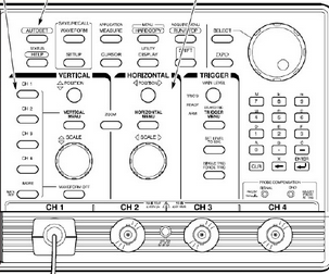
The front panel of the oscilloscope is divided into three main areas, marked as vertical area, horizontal area and trigger area. Due to different modes and types (analog or digital), your oscilloscope may have other areas. Refer to Figure 22, when using an oscilloscope, in order to receive the input signal, the following configuration needs to be adjusted:

Signal attenuation and amplification value: By controlling the volts/div, the amplitude of the signal can be adjusted to the desired measurement range. Time base: By controlling 1 division per second, the amount of time represented by each horizontal scale in the display can be obtained. Oscilloscope triggering: Using the trigger level, you can stabilize a repetitive signal or trigger a single event.
Vertical system and controlThe vertical position and scale of the waveform are regulated by the vertical control part. The vertical control can also set the coupling mode and other signal conditions. General vertical controls include:
Termination equipment: 1M ohm/50 ohm; Coupling mode: DC/AC/GND ground wire, position; offset; transpose one on/off; scale; variable; edit and put; bandwidth limit: 20 MHz. /250 MHz/full bandwidth;

The horizontal system of the oscilloscope is more directly related to the input signal. The sampling rate and record length need to be set here. The horizontal control is used to indicate the position and scale of the waveform in the horizontal direction. General level controls include:
Main time base; Delay time base: XY mode; Scale: waveform trace description distinction; record length; resolution; sampling rate; trigger position; zoom;
Trigger system and controlThe trigger function of the oscilloscope can synchronize horizontal scanning at the correct point of the signal, which is very important for clear signal characteristics. The trigger control can stabilize the repetitive waveform and collect the single pulse waveform.
The trigger enables the repetitive waveform to be stably displayed on the oscilloscope screen by continuously displaying the same part of the input signal. It is conceivable that if the start of each scan starts from a different position of the signal, the image on the screen will be very chaotic, as shown in Figure 35.

Hp Laptop Series,Laptop Parts,Laptop Palmrest,Hp Palmrest
S-yuan Electronic Technology Limited , https://www.syuanelectronic.com