The PWM rectifier circuit is a rectifier circuit composed of a PWM control method and a fully controlled device, which can solve the problems of the conventional rectifier circuit to varying degrees. The SPWM control technology in the inverter circuit is used for the rectifier circuit to form a PWM rectifier circuit. By controlling the PWM rectifier circuit so that its input current is very close to the sine wave and is in phase with the input voltage, the power factor is approximately 1. Therefore, the PWM rectifier circuit is also called a unit power factor converter.
1. Single-phase PWM rectifier circuit
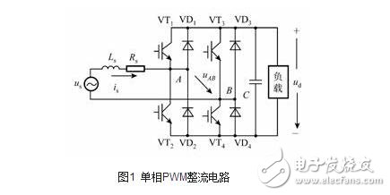
The single-phase bridge PWM rectifier circuit is shown in Figure 1. According to the natural sampling method, SPWM control is performed on the power switching devices VT1 to VT4, and the SPWM wave voltage can be generated between the AC input terminals AB of the full bridge. XML: NAMESPACE PREFIX = V /》 ![]() .
. ![]() It contains the fundamental wave proportional to the amplitude and amplitude of the sinusoidal modulation wave, and the higher harmonics of the carrier frequency, but does not contain the lower harmonics. Due to the action of the input inductor Ls on the AC side, the current ripple caused by the higher harmonics is filtered out, and the frequency of the sinusoidal modulation wave is controlled to be the same frequency as the power source, then the input current is
It contains the fundamental wave proportional to the amplitude and amplitude of the sinusoidal modulation wave, and the higher harmonics of the carrier frequency, but does not contain the lower harmonics. Due to the action of the input inductor Ls on the AC side, the current ripple caused by the higher harmonics is filtered out, and the frequency of the sinusoidal modulation wave is controlled to be the same frequency as the power source, then the input current is ![]() It can also be a sine wave of the same frequency as the power supply.
It can also be a sine wave of the same frequency as the power supply.
The single-phase bridge PWM rectifier circuit works on the principle of boost chopping. When the AC power supply voltage ![]() At the time, two boost chopper circuits are respectively composed of VT2, VD4, VD1, Ls, and VT3, VD1, VD4, and Ls. Take the circuit composed of VT2, VD4, VD1, and Ls as an example. When VT2 is turned on,
At the time, two boost chopper circuits are respectively composed of VT2, VD4, VD1, Ls, and VT3, VD1, VD4, and Ls. Take the circuit composed of VT2, VD4, VD1, and Ls as an example. When VT2 is turned on, ![]() The energy is stored in Ls through VT2 and VD4. When VT2 is turned off, the energy stored in Ls is charged to the DC side capacitor C through VD1 and VD4, causing DC voltage.
The energy is stored in Ls through VT2 and VD4. When VT2 is turned off, the energy stored in Ls is charged to the DC side capacitor C through VD1 and VD4, causing DC voltage. ![]() Above
Above ![]() Peak. when
Peak. when ![]() At the same time, VT1, VD3, VD2, Ls and VT4, VD2, VD3, Ls respectively form two step-up chopper circuits, and the working principle and
At the same time, VT1, VD3, VD2, Ls and VT4, VD2, VD3, Ls respectively form two step-up chopper circuits, and the working principle and ![]() It is similar. Since the voltage-type PWM rectifier circuit is a step-up rectifier circuit, its output DC voltage should be adjusted upward from the peak value of the AC voltage, and the low regulation will deteriorate the input characteristics and may not even work.
It is similar. Since the voltage-type PWM rectifier circuit is a step-up rectifier circuit, its output DC voltage should be adjusted upward from the peak value of the AC voltage, and the low regulation will deteriorate the input characteristics and may not even work.

Input Current ![]() Relative supply voltage
Relative supply voltage ![]() The phase is through the AC input voltage to the rectifier circuit
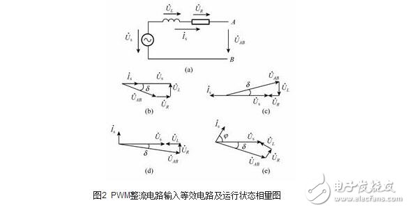
The phase is through the AC input voltage to the rectifier circuit ![]() Control to achieve adjustment. Figure 5-47 shows the fundamental circuit of the AC input loop and the phasor diagram for various operating conditions. In the picture
Control to achieve adjustment. Figure 5-47 shows the fundamental circuit of the AC input loop and the phasor diagram for various operating conditions. In the picture ![]()
![]() AC power supply voltage
AC power supply voltage ![]() ,inductance
,inductance ![]() Upper voltage
Upper voltage ![]() ,resistance
,resistance ![]() Upper voltage
Upper voltage ![]() And input current
And input current ![]() Fundamental phasor,
Fundamental phasor, ![]() for
for ![]() The phasor.
The phasor.
2
Figure (b) shows the PWM rectification state, at this time control ![]() Lag
Lag ![]() one of
one of ![]() Corner to ensure
Corner to ensure ![]() versus
versus ![]() In phase, the power factor is 1, and energy is sent from the AC side to the DC side.
In phase, the power factor is 1, and energy is sent from the AC side to the DC side.
Figure (c) shows the PWM inverter state, at this time control ![]() Advance
Advance ![]() one of
one of ![]() Corner to ensure
Corner to ensure ![]() versus
versus ![]() Just opposite phase, the power factor is also 1, but the energy returns from the DC side to the AC side. As can be seen from Figures (b) and (c), the PWM rectifier circuit only needs to be controlled.
Just opposite phase, the power factor is also 1, but the energy returns from the DC side to the AC side. As can be seen from Figures (b) and (c), the PWM rectifier circuit only needs to be controlled. ![]() The phase can easily realize the bidirectional flow of energy, which is a necessary converter circuit scheme for the AC speed control system which needs regenerative braking function and wants to realize four-quadrant operation.
The phase can easily realize the bidirectional flow of energy, which is a necessary converter circuit scheme for the AC speed control system which needs regenerative braking function and wants to realize four-quadrant operation.
Figure (d) is the reactive power compensation state, at this time control ![]() Lag
Lag ![]() One
One ![]() Corner to ensure
Corner to ensure ![]() Advance
Advance ![]() At 90o, the rectifier circuit sends reactive power to the AC power supply. This operating state circuit is called the reactive power generator SVG (StaTIc Var Generator) and is used for power system reactive power compensation.
At 90o, the rectifier circuit sends reactive power to the AC power supply. This operating state circuit is called the reactive power generator SVG (StaTIc Var Generator) and is used for power system reactive power compensation.
Figure (e) shows the control ![]() Phase and amplitude can be achieved
Phase and amplitude can be achieved ![]() versus
versus ![]() Arbitrary phase
Arbitrary phase ![]() relationship.
relationship.
2. Three-phase PWM rectifier circuit
The structure of the three-phase bridge PWM rectifier circuit is shown in Figure 3. The working principle is the same as that of the single-phase circuit, which is only extended from single phase to three phase. As long as the circuit is subjected to three-phase SPWM control, the three-phase SPWM output voltage can be obtained at the AC input terminals A, B, and C of the rectifier circuit. By controlling each phase voltage according to the phasor diagram of Figure 3(b), a three-phase sinusoidal current input close to the unity power factor can be obtained. The circuit can also operate in an inverting state or in the operating state of Figure 5-47(d), (e).

PWM rectifier circuit control
In order to make the PWM rectifier circuit obtain the control effect of the input current sinusoid and the same phase as the input voltage, the control mode can be divided into two types according to the presence or absence of current feedback: indirect current control and direct current control. Indirect current control does not introduce current feedback, and its dynamic characteristics are poor and less applicable. Direct current feedback is used to calculate the AC input current reference value, and then AC current feedback is used to directly control the input current to track the reference value to obtain the desired input characteristics.

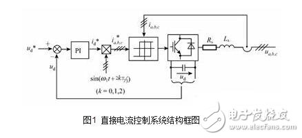
The figure shows a block diagram of the most commonly used current hysteresis comparison direct current control system. This is a double closed loop control system, the outer ring is a DC voltage control loop, and the inner loop is an AC current control loop. DC voltage given? XML: NAMESPACE PREFIX = V /》 ![]() And actual DC voltage
And actual DC voltage ![]() In contrast, the difference signal is sent to the PI regulator for proportional-integral operation to ensure
In contrast, the difference signal is sent to the PI regulator for proportional-integral operation to ensure ![]() Realize dynamic adjustment, static and no difference, its output as DC current reference value
Realize dynamic adjustment, static and no difference, its output as DC current reference value ![]() .
. ![]() Multiply by and three-phase supply voltage
Multiply by and three-phase supply voltage ![]() Sinusoidal signal in the same phase
Sinusoidal signal in the same phase ![]()
![]()
![]()
![]()
![]() After that, obtain the sinusoidal reference value of the three-phase alternating current
After that, obtain the sinusoidal reference value of the three-phase alternating current ![]() They are in phase with their respective supply voltages, and the amplitude is the DC current reference value that reflects the magnitude of the load current.
They are in phase with their respective supply voltages, and the amplitude is the DC current reference value that reflects the magnitude of the load current. ![]() In proportion, this is the AC current reference value required for the rectifier to operate in unity power factor.
In proportion, this is the AC current reference value required for the rectifier to operate in unity power factor. ![]() And feedback of the actual three-phase input current
And feedback of the actual three-phase input current ![]() After comparison, the hysteresis control of each phase power switch enables the actual AC input current to track the reference value to achieve direct feedback control of the input current.
After comparison, the hysteresis control of each phase power switch enables the actual AC input current to track the reference value to achieve direct feedback control of the input current.
The direct current control system using hysteresis current comparison has a simple structure, a fast current response, and the control operation is independent of circuit parameters, and has good robustness, and thus is widely used.
Since AC power cord is output of high voltage electric power, there is a risk of electric shock injury, therefore, All the AC power cord must comply with safety standard to produce. AC (Alternating Current) Power cord is to transmit high voltage. It is used to drive machinery or home appliances.
AC Power cord,power cable, batter cable, power cord
ETOP WIREHARNESS LIMITED , https://www.wireharnessetop.com