The S7-200 SMART instruction provides the following three types of timers.
On-delay timer (TON): used to time a single time interval.
Memory on-delay timer (TONR): used to accumulate the time value of multiple timing intervals.
Off-delay timer (TOF): It is used to extend a certain time interval after the OFF (or FALSE) condition, such as the delay of cooling the motor.
Timer number and resolution
The timer counts the time interval. The timer resolution (time base) determines the length of each time interval.
S7-200 SMART provides 256 timers available for use, that is, the timer number available to the user is T0-T255. TON, TONR and TOF timers provide three resolutions: 1ms, 10ms and 100ms. (Each unit of the current value is a multiple of the time base. For example, when using a 10 ms timer, counting 50 means that the elapsed time is 500 ms).
The resolution (time base) and maximum counting time of the timer number are as follows:
Table 1. Timer number and resolution

The timer number determines the resolution (time base) of the timer, and the resolution is marked on the instruction block.
Note: The same timer number cannot be used for TON and TOF timers at the same time. For example, TON T32 and TOF T32 cannot be used at the same time.
Timers of different resolutions are refreshed according to the following rules:
1ms: 1ms resolution timer, the update of the timer bit and current value is not synchronized with the scan cycle. For a program scan cycle greater than 1ms, the timer bit and current value are refreshed multiple times in a scan cycle.
10ms: 10ms resolution timer, the timer bit and current value are refreshed at the beginning of each program scan cycle. The timer bit and current value are constant throughout the scan cycle. At the beginning of each scan cycle, a scan cumulative time interval is added to the current value of the timer.
100ms: A timer with a resolution of 100ms. The timer bit and current value are refreshed when the instruction is executed. Therefore, in order to ensure the correct timing value, it is necessary to ensure that the 100ms timer instruction is executed only once in a program scan cycle.
Note: To ensure the minimum time interval, increase the preset value (PV) by 1. For example: when using a 100 ms timer, to ensure that the minimum time interval is at least 2100 ms, set the PV to 22.
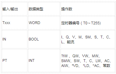
The valid operands of the timer instruction are shown in the following table:
Table 2. Valid operands of timer instructions

Functions of different timers
TON and TONR timer operations:
The timer starts when the enable input IN is turned on. When the current value is equal to or greater than the preset time, the timer position is turned on.
When the enable input is set to disconnect, the current value of the TON timer is cleared.
When the enable input is set to disconnect, the current value of the TONR timer is maintained. When the input IN is set to ON, the TONR timer can be used to accumulate time. Use the reset command (R) to clear the current value of TONR.
After reaching the preset time, the TON and TONR timers continue to time until the maximum value of 32,767 is reached.
TOF timer
When the enable input is turned on, the timer bit is turned on immediately, and the current value is set to 0. When the input is disconnected, the timing starts, and the timing continues until the current time is equal to the preset time.
When the preset value is reached, the timer bit turns off and the current value stops incrementing; however, if the enable input turns on again before the TOF reaches the preset value, the timer bit remains on.
To make the TOF timer start the timed off delay time interval, the enable input must be switched on-off.
If the TOF timer is in the SCR area and the SCR area is inactive, the current value is set to 0, the timer bit is turned off and the current value does not increase.
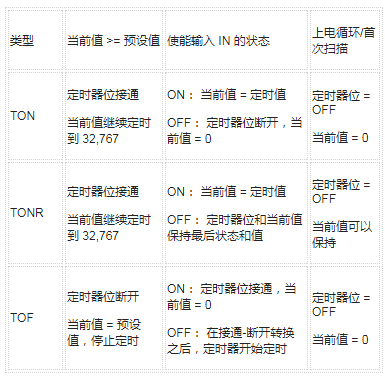
The working rules of timers are shown in the following table:
Table 3. Timer operation and PLC power-on cycle

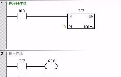
An example of the on-delay timer command is shown in the figure below:

Figure 1. An example of the instruction program for the on-delay timer
among them:
The time base of the timer T37 is 100ms, the preset value is set to 10, and the actual delay time is 100ms×10=1s.

Figure 2. Timing diagram
among them:
When IN is "1" state, the timer starts to run
Delay to reach the preset value, T37 is set
When the IN input is "0", the timer is reset
If there is no reset, the current value continues to increase to the maximum value
The performance of the timer in the subroutine
In the main program of the conditional call subroutine, when the subroutine call is stopped, if the timer has been activated and is timing, stopping the call of this subroutine will cause the timer to run out of control. No matter how the activation conditions in front of the timer change at this time, the timer (1ms, 10ms time base) will reach the maximum value, and the timer output will be turned on when it reaches the set value; (100ms time base timer It will stop timing under the above circumstances, but it is logically out of control).
If SM0.0 is used to call a subroutine; or the timing of the control logic is ensured to ensure the complete execution of the timing function, the timer will run normally. When using conditions to call a subprogram containing a timer, you must pay attention to the sequential logic to avoid program operation errors.
common problem
1. When using a timer-timing program, the compiler reports an error "The memory search range of the instruction operand is invalid"?
This situation is often caused by the inconsistency between the called timer number and the timer type. Refer to the table above. For example, T7 can only be used as TONR, not TON or TOF.
2. Why the timers and counters in the subroutine do not work or work abnormally?
If the following conditions occur:
A. A subroutine that uses a timer or counter internally is called multiple times at the same time
B. Timers or counters with the same number are used by multiple subroutines, and two or more of these subroutines are called at the same time
The timer or counter resources will affect each other due to overlapping use, causing errors in program logic and so on.
USB 3.0 is the future and the new generation in transmission tech, with the following advantages: Super speed – It`s 10 times faster than its predecessor and backward compatible with all USB 2.0 interfaces. It uses a 9-pin connector with 4 pins compatible with USB 2.0 and another 5 pins for bi-directional data transfer.
External Differences
The USB 3.0 connector is blue.
The top 5 pins provide the two-way data transfer.
The bottom 4 pins provide backward compatibility with USB 2.0.
Note: All USB 3.0 Interfaces are blue
Usb 3.0 Cable,Usb3 Cable,3.0 Usb Port,Micro Usb 3.0 Cable
UCOAX , https://www.jsucoax.com