The thermocouple or thermal resistance sensor converts the measured temperature into an electrical signal, and then sends the signal to the transmitter's input network, which contains related circuits such as zero adjustment and thermocouple compensation. The zero-adjusted signal is input to the operational amplifier for signal amplification. The amplified signal is calculated and processed by the V/I converter and then output as a 4-20mA DC current; the other is processed by the A/D converter and displayed on the meter. There are two kinds of linearization circuits for transmitters, and the transmitters all adopt feedback mode. For the thermal resistance sensor, use positive feedback to calibrate, and for the thermocouple sensor, use the multi-segment polyline approximation method to calibrate. The integrated digital display temperature transmitter has two display modes. The temperature transmitter displayed on LCD uses a two-wire system to output, and the temperature transmitter displayed on LED outputs in a three-wire system.
The working principle of the transmitter is that the transmitter sends a signal to the secondary instrument to display the measurement data.
There are many types of transmitters. Generally speaking, the transmitter sends a signal to the secondary instrument to display the measurement data. A device that converts physical measurement signals or ordinary electrical signals into standard electrical signal output or can be output by means of communication protocols. Generally divided into: temperature/humidity transmitter, pressure transmitter, differential pressure transmitter, liquid level transmitter, current transmitter, power transmitter, flow transmitter, weight transmitter, etc. Transmitter follows a physical law (or experimental mathematical model) to convert the change of physical quantity into a standard signal such as 4-20mA. The transmitter is a converter that converts the output signal of the sensor into a signal that can be recognized by the controller. It can also convert the non-electricity input from the sensor into an electrical signal while amplifying it for remote measurement and control.
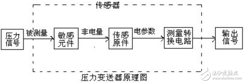
Working principle of pressure transmitterThe working principle of the pressure transmitter is to convert the weak non-electrical pressure-pressure variable collected by the sensor into a standardized signal output that can be transmitted, and at the same time amplify it to provide secondary instruments such as indicator alarms, recorders, and regulators for measurement , Instructions and process adjustment. The converted electrical signal has a certain continuous function relationship with the pressure variable (usually a linear function). The pressure transmitter is mainly composed of three parts: the sensitive element, the sensing element and the measurement conversion circuit. The principle of pressure transmitter is shown in the schematic diagram as follows:

Pressure variables include positive and negative gauge pressure, differential pressure and absolute pressure. Pressure transmitters can be divided into general pressure transmitters 0.001-20MPa and micro-differential pressure transmitters 0-1.5kpa according to the pressure measurement range.
USB Power Sockets, USB Charger, USB Adaptor, Charging USB Ports, USB Quick Charger
NINGBO COWELL ELECTRONICS & TECHNOLOGY CO., LTD , https://www.cowellsockets.com