First, the dormitory intelligent alarm system design
Abstract: The system uses the 16-bit single-chip SPCE061A of Sunplus as the main controller. The smoke sensor and the human pyroelectric infrared sensor respectively sense the smoke and human body infrared signals, and the alarm action is made by the single-chip microcomputer. The design of the system is mainly to meet the needs of the automatic alarm of the dormitory. The design goal is to realize the functions of voice alarm, time setting and display, lighting alarm and network alarm.
1 design plan
1.1 The choice of the main controller
The 16-bit single-chip SPCE061A of Sunplus Company is used as the main controller. Because SPCE061A has 2 KB SRAM and 32 KB memory FLASH, it can meet the requirements of storage password and various data of this system, and the CPU clock frequency is up to 49.152 MHz, which can ensure the fast response, and the built-in voice module is improved. The friendliness of the system man-machine interface.
1.2 Remote monitoring plan selection
Adopt wireless communication. Wireless communication is performed using the wireless transceiver module NRF2401. This communication method is not affected by the length of the line, and the position of the master and slave stations can be arbitrarily set, and the arrangement is relatively flexible.
1.3 Selection of valuables detection plan
The width of the door frame is generally 1~2 m. It is convenient to use the RF transceiver module. The transmitter is attached to the valuables, and the receiver is fixed at the door. When valuables come in and out, it can be recorded. The transmitter and receiver circuit structures are relatively simple, small in size, and easy to carry.
1.4 System overall block diagram
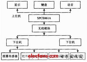
According to the above design ideas, the overall block diagram of the system is shown in Figure 1. The system consists of two parts: the upper computer and the lower computer. The host computer records keyboard input, voice prompts, alarms, and personnel entry and exit. The lower computer performs data collection such as smoke detection, human body infrared detection, valuables detection, and personnel entry and exit detection. The lower computer sends the detection signal to the upper computer through the wireless transceiver module. The host computer performs data processing and acts accordingly.

Figure 1 overall system block diagram
2 Theoretical analysis and calculation
2.1 Calculation of the item detection circuit
The wireless transmission and reception methods are used for the detection of valuables, and the communication distance is related to the transmission power, the receiving sensitivity and the operating frequency. The communication frequency is 8MHz and the inductance is 47μH.

2.2 Analysis of control scheme
According to the requirements of the topic, in order to realize the remote monitoring of the dormitory security situation, the simulation is carried out by means of a master and two slaves. The master station can realize the search of the slave station, display the slave station online in real time, and receive and process the information. , record and alarm, slave station to obtain information and send. The real-time display of the slave information can be realized on the master station, and the alarm and valuables in and out information are stored in the FLASH of the main station, and the external memory chip is omitted, which can be conveniently read and displayed. Use the human body sensor and count the number of people entering and leaving the dormitory to determine the number of people in the dormitory and prompt the door to lock. The internal clock of the MCU is used as the time reference, and the time setting is performed through the keyboard to record the alarm time. The voice module is realized by the voice module inside the single chip microcomputer, which is intuitive and practical. This control scheme makes full use of the on-chip resources of the microcontroller, and uses fewer external devices, which is simple and practical.
2.3 smoke detection module
It adopts MQ-2 smoke sensor, which has the advantages of wide detection range, high sensitivity, fast response recovery, excellent stability and long life. It can realize smoke detection with simple drive circuit. The smoke sensor circuit is shown in Figure 2. When no smoke signal is detected, the comparator outputs a low level; when the sensor detects a smoke signal, the comparator outputs a high level of 5 V and the alarm operates.

Figure 2 Smoke sensor structure
2.4 Human body infrared detection module
The passive infrared human body sensor is constructed by using the chip BISS0001 with a pyroelectric infrared sensor KBS-6B and a small number of external components. The addition of Fresnel lens greatly improves the detection range and satisfies the human detection requirements. When someone passes the pyroelectric sensor, the V. port of the BISS0001 outputs a positive pulse, and the alarm operates. The circuit structure is shown in Figure 3.

Figure 3 Thermoelectric infrared sensor structure
2.5 Personnel access detection design
The two infrared photoelectric switches placed before and after are used to determine the entry/exit of the personnel through the detection of the switching sequence. When someone exits the dormitory, the control signal 1 is set high first, and then the control signal 2 is set high. The judgment of the timing can be used to conclude that the person is out. The same is true when someone enters. The detection circuit is shown in Figure 4.

Figure 4 personnel access detection circuit diagram
2.6 Valuables inspection design
In order to meet the requirements of valuables detection, a single tuned loop resonant amplifier is placed in the card, the card is hung on the valuables, and the card emits an RF signal. When it enters the dormitory, it resonates with the secondary coil and the load voltage changes. By detecting the load, the entry and exit of the personnel can be recorded. The circuit is shown in Figure 5.

Figure 5 Valuables detection circuit diagram
3 programming
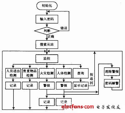
After the main station system is powered on, it is initialized and requires a password. If the password is entered correctly, the fire, valuables, keyboard, etc. can be monitored and processed according to the monitoring situation. After the slave station is powered on, the status of each sensor is monitored and data is transmitted. The program flow is shown in Figure 6.

Figure 6 main program flow chart
4 test data and analysis
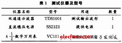
4.1 Test equipment
Test instruments and models are shown in Table 1.

4.2 Test methods and test data
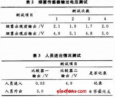
Test methods and test data are shown in Table 2 and Table 3.
The test data in Table 2 shows that the smoke sensor performs well.
The test data shown in Table 3 meets the design requirements.

5 Conclusion
The system has achieved the design requirements through testing. The main innovation is to add a voice alarm function, which is more practical. By adding the slave search function, the working status of each slave station can be displayed in real time; the unattended function is added, and the alarm can be issued immediately after the personnel activity is found in a certain time period; For time setting and display.
GALOCE custom Load Pin Series are compact size load pins designed for tension and compression measurements. Loadpins are force sensors which are being installed in applications for measuring dynamic, static or hoisting forces. They can be applied on clevis pin shackles, loading cranes, lifting fittings, sprockets and pulley axles by replacing existing shear pins, clevis bolts, clevis pins, shear axles and many other types of pinned joints to control or monitor reaction load on the pins.
If you have specific drawing or you want us to design your loadpin, please do not hesitate to contact us. Please send an e-mail to info@galoce.com, fill in your contact information and we will contact you.
Custom Pin Load Cell,Pin Weight Sensor,Shaft Pin Load Cell,Custom Load Cell,Loadpins
GALOCE (XI'AN) M&C TECHNOLOGY CO., LTD. , https://www.galoce-meas.com