The gas sensor is the heart of the gas detection system and is usually mounted in the probe. Essentially, a gas sensor is a transducer that converts a certain gas volume fraction into a corresponding electrical signal. The probe conditioned the gas sample through a gas sensor, typically including filtering out impurities and interfering gases, drying or cooling, sample aspiration, and even chemically processing the sample for faster measurement by the chemical sensor.
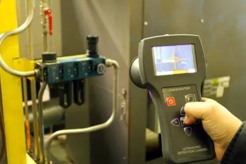
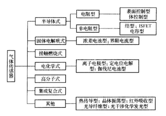
There are many types of gases and different properties, so there are many types of gas sensors. According to the nature of the gas to be tested, it can be divided into: sensors for detecting flammable and explosive gases, such as hydrogen, carbon monoxide, gas, gasoline volatile gas, etc.; sensors for detecting toxic gases, such as chlorine gas, hydrogen sulfide, arsenic, etc.; Sensors for detecting industrial process gases, such as oxygen in steelmaking furnaces, carbon dioxide in heat treatment furnaces; sensors for detecting atmospheric pollution, such as NOx, CH4, O3, which form acid rain, and household pollution such as formaldehyde. According to the structure of the gas sensor, it can be divided into dry type and wet type; according to the output of the sensor, it can be divided into two types: resistive type and resistive type; according to the test institute, it can be divided into electrochemical method, electrical method, optical method and chemistry. Several types of law.
Semiconductor gas sensor
Semiconductor gas sensors are classified into resistive and non-resistive types (junction, MOSFET, and capacitor). The principle of a resistive gas sensor is that gas molecules cause changes in the resistance of sensitive materials; non-resistive gas sensors mainly have M()s diodes and junction diodes and field effect transistors (M()SFETs), which utilize sensitive gases. The principle of changing the MOSFET turn-on voltage is the same as that of the ISFET ion-sensitive sensor.
Resistive semiconductor gas sensorPrinciple of action
It has been found that SnO2, ZnO, Fe2O3, Cr2O3, MgO, NiO2 and other materials have gas sensing effects. The gas sensing film made of these metal oxides is an impedance device, and ions can be exchanged between the gas molecules and the sensitive film to cause a reduction reaction, which causes a change in the resistance of the sensitive film. It is also required as a sensor that this reaction must be reversible, that is, in order to eliminate gas molecules, an oxidation reaction must also occur. The heater inside the sensor helps to oxidize the progress of the reaction. SnO2 thin film gas sensor is currently the mainstream product because of its good stability, ability to work at lower temperatures, inspection of gas types and process maturity. In addition, Fe2O3 is also a widely used and researched material. In addition to the traditional three categories of SnO, SnO2 and Fe2O3, a number of new materials have been researched and developed, including single metal oxide materials, composite metal oxide materials and mixed metal oxide materials. The research and development of these new materials has greatly improved the characteristics and application range of gas sensors.
Selectivity is a key feature of gas sensors. For example, SnO2 film is sensitive to many gases. How to improve the selectivity and sensitivity of SnO2 gas sensing devices has been the focus of research. The main measures are: adding different precious metal or metal oxide catalysts to the base material, setting a suitable working temperature, and filtering the sensitive gas by using a filtering device or a gas permeable membrane. Doping in SnO2 material is the main method to improve sensor selectivity. Adding precious metals such as Pt, Pd and Ir can not only improve the sensitivity and response time of the component, but also cause different adsorption tendencies and improve selectivity. . For example, the doping of noble metals Pt, Pd, Au in SnO2 gas sensitive materials can improve the sensitivity to CH4. Doping Ir can reduce the sensitivity to CH4, doping Pt and Au improve the sensitivity to H2, and doping Pd decreases to H2. Sensitivity.
The operating temperature has an effect on the sensitivity of the sensor. The left figure below shows the resistance characteristics of SnO2 gas sensors for various gas temperatures. It can be seen from the figure that the sensitivity of the device to various gases is different at different temperatures, and this characteristic can be used to identify the gas species.
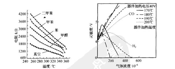
The preparation process also has a great influence on the gas sensing properties of SnO2. If ThO2 is added to SnO2, the sintering temperature and heating temperature can be changed to produce different gas sensing effects. According to the mass calculation, add 3 to 5% of ThO2 and 5% of Sm2 to SnO2. Sintering was carried out in an H 2 atmosphere at 600 ° C to form a thick film device, and the operating temperature was 400 ° C. It can be used as a CO detection device. The figure on the right is the characteristics of the gas sensor at a sintering temperature of 600 °C. It can be seen that the operating temperature is in the range of 170-200 ° C, and the sensitivity curve to H2 is parabolic, but has little effect on the changing operating temperature of CO. Therefore, the characteristics of the device can be used to detect H2. When the sintering temperature is 400 °C, the sensitivity curve of H2 and CO is approximately straight when the operating temperature is 200 °C, but the sensitivity to CO is much higher, and the CO sensor sensitive to CO can be made. .
Structure and parameters
SnO2 resistive gas sensors are usually sintered. Porous SnO2 ceramics are used as the base material, and different other substances are added, and sintered by a ceramic process. The heating resistor wire and the measuring electrode are buried during sintering. In addition, thin film devices and multilayer film devices fabricated by processes such as evaporation and sputtering are also available, and such devices have high sensitivity and good dynamic characteristics. There are also thick film devices and mixed film devices made by screen printing. These devices have the advantages of high integration, easy assembly, convenient use, and convenient mass production.
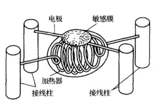
The following figure is a typical structure of a resistive gas sensor. It consists mainly of South SnO2 sensitive components, heaters, electrode leads, bases and stainless steel mesh. The sensor has a simple structure and is convenient to use, and can detect a reducing gas, a combustible gas, a vapor, and the like.
The main characteristic parameters of the resistive gas sensor are:
1. Inherent resistance R0 and working resistance Rs
The inherent resistance Ro, also known as the normal resistance, represents the resistance of the gas sensor under normal air conditions. The working resistance Rs represents the resistance of the gas sensor in a certain concentration of the measured gas.
2, sensitivity S
It is usually expressed by S=Rs/R0, and sometimes by the ratio of the resistance values ​​of the elements in the gas at two different concentrations C1 and C2): S=Rs(C2)/R0(C1).
3, response time T1
Reflecting the dynamic characteristics of the sensor is defined as the time it takes for the resistance of the sensor to reach a stable value at that concentration from a certain concentration of gas. It is also often used when the time to reach 63% of the change rate of the resistance value at this concentration is used.
4. Ask T2 when recovering
Also known as the desorption time. Reflecting the dynamic characteristics of the sensor is defined as the recovery time from when the sensor is removed from the detection gas until the resistance of the sensor returns to normal air conditions.
5, heating resistor RH and heating power PH
RH provides the heating wire resistance of the operating temperature of the sensor, and PH is the heating power required to maintain the normal operating temperature.
Resistive gas sensors have the advantages of low cost, simple manufacturing, high sensitivity, fast response, long life, low sensitivity to humidity, and simple circuit. The inadequacy is that it must work at high temperature, the selectivity to gas is poor, the component parameters are dispersed, the stability is not ideal, the power requirement is high, and when the detection gas is mixed with sulfide, it is easy to be poisoned.
Non-resistive semiconductor gas sensorNon-resistive types are also a relatively common type of semiconductor gas sensing devices. These devices are easy to use, do not require a set operating temperature, are easy to integrate, and are widely used. There are two main types of junction and MOSFET type.
Junction gas sensor
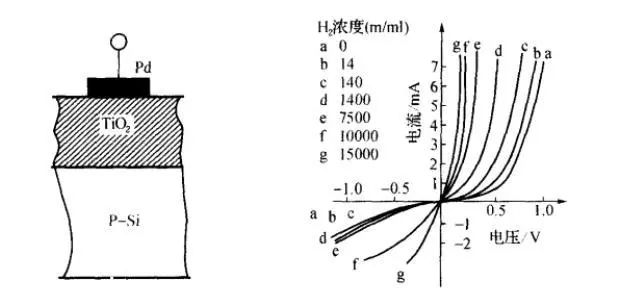
Junction-type gas sensor devices, also known as gas-sensitive diodes, operate on the rectifying characteristics of gas-changing diodes. Its structure is shown in the left figure below. Its principle is that the noble metal Pd is selective for hydrogen, which forms a contact barrier with the semiconductor. When the diode is forward biased, the electrons flowing from the semiconductor to the metal will increase, so the forward direction is conductive. When a negative bias is applied, there is substantially no change in carriers, which is the rectifying characteristic of the Schottky diode. In the detection atmosphere, due to the adsorption of hydrogen, the work function of the precious metal changes, and the contact barrier weakens. As a result, the number of carriers increases, the forward current increases, and the rectification characteristic curve of the diode shifts to the left. The right picture below shows the characteristic curve of Pd—TiO2 gas sensor diode in air with different concentrations of H2. Therefore, the hydrogen concentration can be detected by measuring the forward current of the diode.
MOSFET type gas sensor
The left shift of the characteristic curve of the gas sensor can be seen as a change in the diode turn-on voltage. This characteristic, if it occurs at the gate of the FET, will cause the threshold voltage UT of the FET to change. Using this principle, a MOSFET type gas sensor can be fabricated.
A hydrogen-sensitive MOSFET is one of the most typical gas-sensitive devices, which is made of palladium grid with metal palladium (Pd). In an atmosphere containing hydrogen, due to the catalytic action of palladium, hydrogen molecules are decomposed into hydrogen atoms and diffuse to the interface between palladium and silica, eventually leading to a change in the threshold voltage UT of the MOSFET. The gate leakage is often shorted during use to ensure that the MOSFET operates in a saturated region. At this time, the drain current ID = β (UGS - UT) 2, and the concentration of hydrogen can be measured by this circuit.
The characteristics of hydrogen-sensitive MOSFETs are:
1, sensitivity
When the hydrogen concentration is low, the sensitivity of the hydrogen sensitive MOSFET is very high, and the concentration of hydrogen in 1 ppm changes, and the value of ΔUT can reach 10 mV. When the hydrogen concentration is high, the sensitivity of the sensor is lowered.
2. Selectivity for gases
The "void" between the palladium atoms just allows the hydrogen atoms to pass through. Therefore, the palladium grid allows only hydrogen to pass through and has good selectivity.
3, response time
The response time of this device is affected by temperature and hydrogen concentration. Generally, the higher the temperature, the higher the hydrogen concentration, the faster the response, and the response time at normal temperature is several tens of seconds.
4, stability
In practical applications, there is a characteristic that the UT drifts with time. For this reason, the UT drift can be significantly improved by growing a layer of SiO2 insulating layer in a HCl atmosphere.
In addition to hydrogen, other gases cannot pass through the palladium grid. Pd-MOSFET gas sensors that make other gases should adopt certain measures. For example, when making a CO-sensitive MOSFET, a small hole of about 20 nm should be formed on the palladium grid to allow CO gas to pass. . In addition, since the Pd-MOSFET has high sensitivity to hydrogen and low sensitivity to CO, a layer of aluminum having a thickness of about 20 nm can be evaporated on the palladium gate as a protective layer to prevent hydrogen from passing. The catalytic effect of palladium on the decomposition of ammonia is weak. To this end, a layer of active metal such as Pt, Ir, La, etc. is precipitated on the SiO2 insulating layer. A palladium gate can be fabricated to form an ammonia gas sensitive MOSFET.
Solid electrolyte gas sensorThe solid electrolyte is a solid substance having the same ion conductive property as the aqueous electrolyte solution, and when used as a gas sensor, it is a battery. It does not need to dissolve the gas through the gas permeable membrane to avoid problems such as solution evaporation and electrode consumption. Because of its high conductivity, sensitivity and selectivity, this sensor has been widely used in petrochemical, environmental protection, mining, food and other fields. Its importance is only secondary metal-oxide-semiconductor gas sensor.
Solid electrolyte oxygen sensor principle
The isomer electrolyte will have significant conductivity at high temperatures. Zirconia (ZrO2) is the material of a typical gas sensor. Pure zirconia is monoclinic at normal temperature. When the temperature rises to about 1000 °C, homomorphic transformation occurs, changing from monoclinic structure to polycrystalline structure, accompanied by volume shrinkage and endothermic reaction. Therefore it is an unstable structure. A stabilizer such as alkaline earth calcium oxide CaO or rare earth yttrium oxide Y2O3 is added to ZrO2 to make it a stable fluorite cubic crystal, and the degree of stability is related to the concentration of the stabilizer. ZrO2 is sintered in a l800 ° C atmosphere after adding a stabilizer, and a part of zirconium ions are replaced by calcium ions to form (ZrO·CaO). Since Ca2+ is a positive divalent ion, Zr4+ is a positive tetravalent ion. In order to continue to maintain electrical neutrality, oxygen ions O2-holes are generated in the crystal, which is the reason why (ZrO·CaO) transmits oxygen ions at high temperatures. (ZrO·CaO) is a conductor of oxygen ions at 300 to 800 °C. However, in order to truly transmit oxygen ions, it is necessary to have different oxygen partial pressures (oxygen difference) on both sides of the solid electrolyte to form a concentrated cell. The structural principle is shown in the figure, the two sides are porous precious metal electrodes, and the sandwich structure is made with the dense ZrO·CaO material.
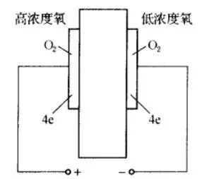
The partial pressures of oxygen on both sides of the electrode are PO2(1) and PO2(2), respectively, and the following reactions occur at the two electrodes:
(+) pole: PO2(2), 2O2-→O2+4e
(-) pole: PO1(1), O2+4e→2O2-
The electromotive force of the above reaction is expressed by the Nernst equation:

It can be seen that at a certain temperature, PO2(1) is fixed, and the above formula can be used to determine the concentration of oxygen to be measured at the sensor (+) pole.
The fixed PO2 (1) is actually a (-) electrode forming a fixed potential electrode, that is, a reference electrode, a gas reference electrode and a coexisting phase reference electrode. The gas reference electrode can be air or other mixed gas, such as: H2 - H2O, CO - CO2 can also form a fixed PO2 (1). The coexisting phase reference electrode refers to a mixed powder of a metal-metal oxide, a low-valent metal oxide-high-valent metal oxide (solid phase), and these mixtures are mixed with oxygen (gas phase) to cause an oxidation reaction to form a predetermined oxygen pressure. Can also be used as a reference electrode.
In addition to oxygen measurement, solid electrolyte sensors such as β-Al2O3, carbonate, and NASICON can be used to measure gases such as CO, SO2, and NH4. In recent years, gas sensors such as tannic acid and La3F which can be used at low temperatures have appeared, and can be used for detecting positive ions.
Infrared gas sensorPrinciple of action
Molecules composed of different atoms have unique vibration and rotational frequencies. When they are exposed to infrared rays of the same frequency, infrared absorption occurs, which causes changes in infrared light intensity. Gases can be measured by measuring changes in infrared intensity. Concentration; it should be noted that vibration and rotation are two different forms of motion. These two forms of motion will correspond to different infrared absorption peaks, and the vibration and rotation itself are also diverse; therefore, in general, there will be multiple gas molecules. Infrared absorption peak; according to the position of a single infrared absorption peak, only the groups in the gas molecule can be determined. To accurately determine the gas type, it is necessary to look at all the absorption peak positions of the gas in the mid-infrared region, that is, the infrared absorption fingerprint of the gas. However, under known environmental conditions, the type of gas can be roughly determined based on the position of a single infrared absorption peak. Since all materials above 273 degrees Celsius or absolute zero will produce infrared radiation, infrared radiation is positively correlated with temperature. Therefore, like the catalytic element, in order to eliminate the change of infrared radiation caused by environmental temperature changes, infrared gas sensor It will consist of a pair of infrared detectors.
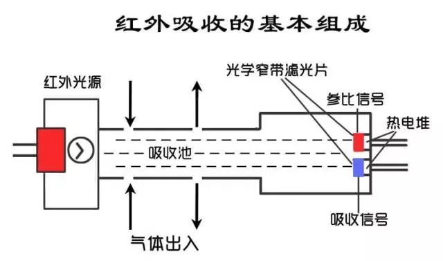
A complete infrared gas sensor consists of an infrared source, an optical cavity, an infrared detector, and a signal conditioning circuit.
Why can't infrared gas sensors measure gas molecules composed of the same atoms such as oxygen, hydrogen, and nitrogen?
The moon and the earth, the earth and the sun are connected by universal gravitation, and the atoms inside the molecule are connected by chemical bonds. If the two are ideal spheres and there is no other gravitational interference, the earth's orbit will be round. In fact, the above two conditions are not true, so the orbit is elliptical, that is, the distance between the earth and the sun is constantly at a short radius. The transition between the long radius and the long radius is vibration, but the vibration period is up to one year. In this process, when the earth is at the short radius point and the long radius point, the gravitational force between it and the sun is different, that is, the energy level is different. In the interior of the molecule, the atoms are connected by chemical bonds. The spatial distance, angle and direction between the atoms change continuously due to the imbalance of the electron distribution, that is, vibration and rotation, and different molecules have unique vibration and rotational frequency. When the infrared radiation of the same frequency is irradiated, resonance, interatomic distance, and electron distribution change, that is, the dipole moment changes, and infrared absorption is generated as such (ultraviolet absorption is the same).
The above contains two basic conditions of infrared absorption: resonance, dipole moment change. These two conditions are met at the same time to produce infrared absorption.
Why do oxygen, hydrogen, nitrogen and other molecules composed of the same atom have no infrared absorption peaks: two basic conditions are that the vibration frequency of the gas molecules is the same as the infrared frequency of the irradiation, and the dipole moment changes. It is not difficult to understand that the first condition is easy to satisfy and the second condition is impossible.
The positive and negative charge centers of the same atom form completely overlap, that is, the dipole moment is zero. As a result, the distribution of electrons in the molecule is balanced. The infrared light itself has low energy density characteristics, and its illumination does not change the equilibrium. It is even less likely that the molecules will be ionized, that is, they will not cause energy changes. The molecules composed of different atoms: taking water (vapor) molecules as an example, the distribution of electrons in the molecule is biased toward the end of oxygen, that is, the hydrogen end of the water molecule is positively charged, and the oxygen end is negatively charged, positive and negative charge center. It does not overlap, that is, the dipole moment is not zero. This is because the ability of oxygen to attract electrons is stronger than that of hydrogen.
When irradiated with infrared rays having the same vibration frequency and rotational frequency as water molecules, the distribution of electrons in the water molecules is more toward the oxygen end, resulting in a shorter average distance between hydrogen and oxygen, that is, the dipole moment becomes shorter and the energy becomes higher, that is, When water molecules are exposed to infrared light, they will transition from low energy levels to high energy levels, and infrared absorption is produced as such. It can be simply understood that when infrared rays meet with molecules of the same atomic origin, since the molecules of the same atom are ideal elastic spheres, the interaction between the two is a completely elastic collision, only energy exchange, and no energy transfer. The interaction of molecules of different atoms with infrared rays has energy transfer. Therefore, the infrared absorption principle cannot measure molecules composed of the same atom.
Non-dispersive infrared absorption gas sensorNon-dispersion: White light is divided into seven colors of light, red, orange, yellow, green, blue, blue, and purple. This prism is a splitting system that separates 7 colors of light. The optical system with the spectroscopic system is a dispersive optical system, and the optical system without the spectroscopic system is non-dispersive. Non-dispersive systems are simple, reliable, compact, and inexpensive. The white light, ultraviolet light, and infrared light that we usually feel are light of different frequencies and wavelengths; single-frequency, single-wavelength light is monochromatic light. It is said that only the frequency of infrared rays and the vibration and frequency of gas molecules will produce infrared absorption. Theoretically, when designing a gas sensor, we want to use monochromatic light to illuminate the gas or after irradiation, we use a grating (filter). The way to get monochromatic light.
Non-dispersive infrared gas sensors typically consist of a light source, an optical cavity, a filter (grating), a detector, and a signal conditioning circuit in which the filter and detector are integrated.
Infrared gas sensor advantages:
1. All gases can be measured except for gases of the same atomic composition.
2, the full range.
3. The sensing process itself does not interfere with sensing.
Disadvantages:
1, expensive. The infrared gas sensor is essentially a temperature sensor that causes the temperature of the detector to change and thus changes the electrical properties of the infrared radiation. The sensing process is complicated. The system is required to have the following characteristics: the light source must have stable infrared radiation; the optical cavity is stable in physical and chemical properties; the filter and the infrared detector are stable. These problems, reasonable process technology itself can be better solved, but the manufacturing cost is high, resulting in high price.
2. In the ordinary design of broadband infrared light source plus filter plus detector, the filter itself cannot achieve ideal selective filtering, so interference, especially water interference, has always existed. The underlying cause of the selectivity problem is that many different gas molecules have the same chemical bond, ie, similar or even overlapping infrared absorption.
3, dust, background radiation, strong adsorption and gas, liquid, solid and easy to change the detection object will have an impact on the test results.
Catalytic combustion gas sensor
Principle of action
Generally, a high-purity platinum coil with a wire diameter of 15um or 20um or 30um is wrapped around the carrier catalyst. Under certain temperature conditions, when the flammable gas contacts the sphere, the adsorbed oxygen on the surface thereof is severely absent. The flame combustion reaction, the heat released by the reaction causes the temperature of the platinum coil to change, and the temperature change causes the platinum coil resistance to change, and the gas concentration can be measured by measuring the resistance change.
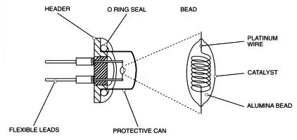
Therefore, instead of saying that the catalytic element is a gas sensor, it is a temperature sensor. To overcome the interference caused by environmental temperature changes, the catalytic elements will form a complete component in pairs, one of which responds to the gas and the other to the other. The gas does not react, but only reacts to the ambient temperature, so that the two components can be mutually opposed to eliminate the interference caused by the change of ambient temperature.
Unlike semiconductor components, the sensing process of catalytic components is more complicated. The former is the chemical reaction that occurs after the gas contacts the sensor, which directly leads to the change of the sensor resistance, that is, the electrical signal. The latter is the first chemical reaction of the gas on the catalytic element. The result is a temperature change on the surface of the sensor carrier and inside the carrier. The temperature change of the carrier undergoes heat transfer and eventually causes a change in the resistance of the platinum coil to complete the entire sensing process.
Problem
The sensing process is complex and the chances of causing problems are greater.
1. For long-chain molecular organics and unsaturated hydrocarbons, for semiconductors, carbon deposition caused by incomplete reaction will only affect the reaction process, and will not have a large impact on electron transport. For catalysis, The presence of carbon not only affects the reaction process, but also has a drastic effect on heat transfer. As a result, the heat generated by the reaction is reduced to the inside of the sensor, and the heat is mostly lost. Finally, the same gas concentration releases the same heat. Due to the presence of char, the sensor: there is only a small change in temperature, ie the sensitivity becomes very low.
2. Because heat transfer is required, in order to ensure thermal efficiency, the reaction must be completed in an instant, that is, a very high reaction efficiency is required, and a large number of nano-scale catalysts and nano-scale pores are required, and such characteristics are advantageous for sensing. Conducive to poisoning.
3. The linearity of the catalytic element is determined by two factors. a. The resistance-temperature characteristic of the temperature sensing material pt coil is linear. b. The reaction exotherm and gas concentration within the lower explosion limit are linear. Therefore, any change in either of these factors can result in a linear change in the sensor. In fact, the platinum coil will continue to sublimate and become thinner, that is, the conductive resistance becomes larger; the linear relationship between the heat released by the reaction and the concentration is only established when the gas concentration is within the lower explosion limit.
future developmentThe future of catalytic components depends primarily on advances in process technology:
1. Structural improvement, the problem solved is the drift caused by vibration.
2, the filter layer is improved, the problem solved is poisoning.
3. Develop new materials to improve carbon deposition.
4. The manufacturing process guarantees the realization of the design, such as avoiding deformation.
5. MEMS. It should be noted that improvements in device structure, packaging, and manufacturing processes will not only improve the overall performance of the components, but also lead to new applications. Compared with semiconductors, the dilemma of catalytic element MEMS is how to have higher catalytic efficiency and thermal efficiency at a small surface area.
6, the application of the catalytic element positioning will be more precise and specific.
7, catalytic components will not be eliminated.
Electrochemical sensorsElectrochemistry is the discipline that studies the relationship between electrical and chemical behavior. The most important application of this discipline is the efficient conversion between electrical energy and chemical energy and high power density storage technology. We know that a sensor is essentially an energy conversion device, such as a pressure sensor that converts mechanical energy into electrical energy. Therefore, it is easy to understand that an electrochemical gas sensor is a battery called a gas fuel cell.
The most common type of battery is a set of electrically conductive chemicals that are inserted into two electrodes of different materials that are electrically connected by wires. Taking a lead-acid battery as an example, an aqueous solution of sulfuric acid is a conductive chemical substance. Lead is placed therein, and electricity is generated at the place where the lead and sulfuric acid are in contact (interface), and the lead oxide is put in, and the interface is also charged. There is a difference in electricity, that is, there is voltage. When wires are connected, electrons will flow from lead to lead oxide, lead will become lead oxide, and lead oxide will become lead oxide. The amount of electricity is related to the amount of chemical and the reaction process.
The most important concept here is that the insertion of a conductor into a conductive chemical creates an electrical potential at the interface, and the insertion of different conductors into the same material produces different potentials. The second is that different potentials are connected and a reaction occurs at the interface. Third, the conductive loop consists of a battery and an external conductor. The outside of the battery is an electron in the connecting wire, and the inside of the battery is an ion. That is, the conductive process is completed by electron movement and ion movement.
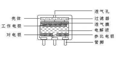
The electrochemical CO gas sensor is a chemical battery or a CO fuel cell. Wherein: CO is a pole (working electrode) that supplies electrons, oxygen is a pole that acquires electrons, and an aqueous solution of sulfuric acid is an electrolyte. The biggest difference from lead-acid batteries is the difference in electrode materials. The electrochemical gas sensor (co) electrode material is gas, and the lead-acid battery is solid. The electrode of the electrochemical gas sensor is called a gas electrode. In the electrochemical CO gas sensor, the working electrode CO acts as a pole for electron supply, and only the CO and the aqueous solution of sulfuric acid are incapable of releasing, collecting and conducting electrons. The process by which a CO completes the process of providing electrons requires the reduction of the difficulty of CO supply of electrons under electrocatalytic conditions. In practice this condition is provided by a porous platinum electrode (or other electrocatalytic conductive electrode). Second, the electrons supplied by the CO need to be conducted after the conductor is collected, and also by the porous platinum electrode.
Similarly, a porous platinum electrode is also required as an oxygen electrode for the counter electrode to assist in obtaining electrons. The platinum electrode is actually the reaction platform. Although the electrochemical sensor sensing principle is simple, it is difficult to achieve reliable and accurate sensing: one requires a stable porous structure of the platinum electrode, the number of holes is sufficient, the aqueous solution of sulfuric acid enters the hole, and CO (or oxygen) is also It can enter the hole and complete the electron supply at the position where the gas (CO)-solid (pt)-liquid (water in the aqueous sulfuric acid solution) is in common contact, that is, the three-phase interface. Therefore, how the three-phase interface remains stable under long-term immersion in sulfuric acid, electrochemical reaction shock, and electrophoresis is the core of reliable and accurate sensing. Second, the aqueous sulfuric acid solution should be stable, non-volatile, non-absorbent, and non-leaking. Any change in the mass of the aqueous solution of sulfuric acid will result in a change in the internal pressure of the sensor, which in turn will cause a change in the three-phase interface. Third, the contact stress of the electrode and the aqueous solution of sulfuric acid determined by the physical properties of the package and the material should be stable.
At present, the main problems of electrochemical sensors are basically due to the above factors. One of the core technologies and processes of electrochemical sensors is how to construct a reasonable and reliable electrode with a physical structure, which is closely related to sensitivity, response recovery, life and temperature characteristics. The second is packaging. Electrochemical sensors have problems such as water loss under dry conditions, water leakage under high humidity conditions, inactivation of poisoning caused by long-term exposure to the gas to be measured, and deactivation due to disintegration of the electrode pore structure. It is characterized by leakage of liquid, short life (compared to other principles), and large volume. It is reflected in the design, the process is complicated, and the manufacturing cost is high.
The future of electrochemical sensors: The clear direction is the solidification of the electrolyte at room temperature and the realization of MEMS based on this. Electrochemical sensors that achieve solid state and MEMS can not only overcome most of the problems including manufacturing, but also stimulate new applications and bring new growth to the enterprise. The electrochemical sensor at this time will be a highly integrated, easy-to-integrate, compact electronic system. However, such results still do not overcome the high performance or sensor performance changes caused by the long-term contact of the measured gas with the sensor.
PID - Photoionization DetectorThe PID consists of an ultraviolet light source and a gas chamber. The principle of ultraviolet light emission is the same as that of fluorescent tubes, but the frequency is high and the energy is large. After the gas to be measured reaches the gas chamber, the ultraviolet photoion emitted by the ultraviolet lamp generates a charge flow, and the gas concentration is positively correlated with the magnitude of the charge flow, and the gas concentration can be measured by measuring the charge flow.
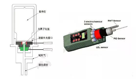
Special gases: physical forms are variable, chemical processes and reaction products are complex and diverse. Including inorganic gases such as ammonia. Organic gases such as toluene.
The various gas sensors introduced above face enormous challenges in the detection of complex gases. For example, the detection of organic vapor, the principle of infrared absorption is difficult to overcome: a, organic vapor due to the large molecular weight, the characteristic absorption wavelength is longer, the energy change after infrared absorption is small, usually the sensitivity will be very low. b. The organic vapor of the long molecular chain is easily adsorbed and adheres to the detector to destroy the light transmission. c, can not achieve the detection of the total amount of voc. If the infrared system realizes the total evaluation, it needs a full-spectrum response filter, detector and full-spectrum infrared light source. This requirement is not only difficult to achieve, even if it is realized, the interference of inorganic gas and water will be logical in the whole spectrum. . In chemical sensors, semiconductors are easily interfered by inorganic gases, temperature and humidity, drifting, and the concentration resolution is low. Although the detection range is wide and the types of gas covered are large, they are still only suitable for low-end applications. In this context, PlD is a better choice for industrial site voc detection.
The biggest feature of other sensors plD is that it is sensitive to only a small amount of inorganic gases such as ammonia and phosphine. The reason is that most inorganic gases have high ionization energy (greater than 11.7 ev). At present, the highest UV radiation energy of the plD lamp is only 11.7 ev. Therefore, in the petrochemical park, the response of PiD can be considered as the response of voc.
PID working principle
1. Fill the vacuum glass chamber with high-purity rare gases such as argon and helium.
2. The glass cavity is sealed with a UV transparent sheet of magnesium fluoride single crystal, wherein the magnesium fluoride crystal is transparent to ultraviolet light.
3. Put the electrode on the outer wall of the glass cavity.
4. Add the electrode and electric field to the magnesium fluoride window as the gas chamber to be tested. This is a complete ionizable VOC UV lamp. During operation, a high-frequency electric field is applied outside the glass cavity. The rare gas in the ultraviolet lamp is ionized by the applied electric field to emit electrons and ions. When the electrons and ions are combined, the ultraviolet light radiates energy outward. The ultraviolet light passes through the magnesium fluoride window to reach the gas chamber, and the gas to be measured in the gas chamber is separated by ultraviolet photoion to generate electrons and ions, and the electric charge generates electric current under the action of the electric field, and can be measured.
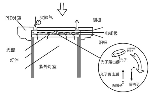
PlD stable work requires:
1. The PID must radiate enough energy to ionize the gas to be measured;
2. The high frequency electric field that produces ultraviolet light must be stable.
3. There should be no impurity gas in the glass cavity, and the impurity gas will cause additional ionization, which will affect the efficiency of ultraviolet light emission.
4. The ultraviolet spectrum is stable and uniform.
5. The transmission of ultraviolet light to the gas chamber is stable and uniform, and does not interact with the metal electrode material constituting the gas chamber to produce heavy metal deposition. The deposition of heavy metal in the ultraviolet radiation window blocks the ultraviolet from reaching the gas chamber.
This requires that the luminescent material charged by the UV lamp must be a gas to be uniformly illuminated and transmitted. There should be no impurity gas in the cavity to prevent additional ionization and the like. These requirements determine that the choice of luminescent gas can only be a rare gas. The window material must be transparent to UV and have stable physicochemical properties. In fact, the choice of UV window material is extremely limited. These limitations and conditions ultimately determine the limitations of PID applications.
Why is the current PID not measuring propane, ethane, methane and most inorganic substances?
The essence of PID is to measure the charge flow after ionizing the measured substance, and ionization requires energy. The most common UV radiation energy of the current PID is 8.3 ev, 9.8 ev, and 10.6 ev. The energy required for ionizing methane is 12.6 ev, ethane is 11.56 ev, propane is 10.95 ev, carbon dioxide is 13 ev, and the like. In fact, people want to develop a higher energy PID, but the condition is that the type of rare gas is extremely limited. The ultraviolet wavelength (energy) is determined by the electronic energy level of the rare gas itself, and humans cannot change it; another limit The condition is that the ultraviolet light transmission window material of a specific wavelength, which wavelength of ultraviolet light can be transmitted depends on the lattice constant of the window material, and the selection in the current material system is also extremely limited. Although people have developed 11.7 ev illuminants, the suitable window material is only lithium fluoride (LiF), and lithium fluoride is very easy to absorb water, resulting in a PID life of 11.7 ev for only two months. That is to say, the current ultraviolet lamp cannot detect substances with higher ionization energy such as methane due to the limitation of output energy.
Why is PID not selective?
If the UV radiation energy of the PID we choose is 10.6 ev, it means that all gas molecules with ionization energy less than 10.6 ev in the measured environment will be ionized. The charge flow we measured is the sum of the charge flows of all ionized gases. Instead of a charge flow of a certain gas. PID non-selectivity is determined by this.
When the PID is working, the materials in the gas chamber will be composited and restored when the ionized substances meet. Long-chain molecules and dust will deposit on the surface of the window. In addition, the ion current generated by the sensor during the operation of the sensor will also deposit heavy metal in the window. On the surface, this obviously affects the transmission of ultraviolet light, which causes zero drift and reduced sensitivity, which affects the detection results. In fact, in addition to the preparation technology of the PiD lamp and the design of the air chamber, the cleaning technology of the UV light through the window of the PID lamp is also one of the core technologies.
The future of PID
1. PiD as an ideal non-radioactive ion source will always exist;
2. Increasing the degree of vacuum before filling the PID lamp and the purity of the filling gas to improve luminous efficiency and luminous stability;
3. Develop new window materials and processing precision to improve light transmittance, uniformity of emitted light, package quality, stability and longevity;
4. Preventing dispersion causes heavy metal deposition in the window and prolonging the life;
5. Window cleaning technology to prevent the deposition of macromolecular organic matter and small particles;
6. Development of long-life PID lamps with higher output energy;
7, small size.
The development direction of gas sensorsThe research of gas sensors involves a wide range of difficulties and is a multidisciplinary research content.è¦åˆ‡å®žæé«˜ä¼ æ„Ÿå™¨å„æ–¹é¢çš„æ€§èƒ½æŒ‡æ ‡éœ€è¦å¤šå¦ç§‘ã€å¤šé¢†åŸŸç ”究工作者的ååŒåˆä½œã€‚æ°”æ•æ料的开å‘å’Œæ ¹æ®ä¸åŒåŽŸç†è¿›è¡Œä¼ 感器结构的åˆç†è®¾è®¡ä¸€ç›´å—åˆ°ç ”ç©¶äººå‘˜çš„å…³æ³¨ã€‚æœªæ¥æ°”ä½“ä¼ æ„Ÿå™¨çš„å‘展也将围绕这两方é¢å±•å¼€å·¥ä½œã€‚具体表现如下:
æ°”æ•æ料的进一æ¥å¼€å‘一方é¢å¯»æ‰¾æ–°çš„æ·»åŠ å‰‚å¯¹å·²å¼€å‘çš„æ°”æ•æ料性能进行进一æ¥æ高;å¦ä¸€æ–¹é¢å……分利用纳米ã€è–„膜ç‰æ–°ææ–™åˆ¶å¤‡æŠ€æœ¯å¯»æ‰¾æ€§èƒ½æ›´åŠ ä¼˜è¶Šçš„æ°”æ•æ料。
æ–°åž‹æ°”ä½“ä¼ æ„Ÿå™¨çš„å¼€å‘å’Œè®¾è®¡æ ¹æ®æ°”体与气æ•ææ–™å¯èƒ½äº§ç”Ÿçš„ä¸åŒæ•ˆåº”è®¾è®¡å‡ºæ–°åž‹æ°”ä½“ä¼ æ„Ÿå™¨ã€‚è¿‘å¹´æ¥è¡¨é¢å£°æ³¢æ°”ä½“ä¼ æ„Ÿå™¨ã€å…‰å¦å¼æ°”ä½“ä¼ æ„Ÿå™¨ã€çŸ³è‹±æŒ¯åå¼æ°”ä½“ä¼ æ„Ÿå™¨ç‰æ–°åž‹ä¼ 感器的开å‘æˆåŠŸè¿›ä¸€æ¥å¼€é˜”了设计者的视野。目å‰ä»¿ç”Ÿæ°”ä½“ä¼ æ„Ÿå™¨ä¹Ÿåœ¨ç ”ç©¶ä¸ã€‚
æ°”ä½“ä¼ æ„Ÿå™¨ä¼ æ„Ÿæœºç†çš„进一æ¥ç ”究新的气æ•ææ–™å’Œæ–°åž‹ä¼ æ„Ÿå™¨å±‚å‡ºä¸ç©·ï¼Œå¾ˆæœ‰å¿…è¦åœ¨ç†è®ºä¸Šå¯¹å®ƒä»¬çš„ä¼ æ„Ÿæœºç†è¿›è¡Œæ·±åº¦çš„ç ”ç©¶ã€‚åªæœ‰æœºç†æ˜Žç¡®äº†ï¼Œä¸‹ä¸€æ¥çš„工作æ‰ä¼šå°‘走弯路。
æ°”ä½“ä¼ æ„Ÿå™¨çš„æ™ºèƒ½åŒ–ç”Ÿäº§å’Œç”Ÿæ´»æ—¥æ–°æœˆå¼‚çš„å‘å±•å¯¹æ°”ä½“ä¼ æ„Ÿå™¨æ出了更高的è¦æ±‚ï¼Œæ°”ä½“ä¼ æ„Ÿå™¨æ™ºèƒ½åŒ–æ˜¯å…¶å‘å±•çš„å¿…ç”±ä¹‹è·¯ã€‚æ™ºèƒ½æ°”ä½“ä¼ æ„Ÿå™¨å°†åœ¨å……åˆ†åˆ©ç”¨å¾®æœºæ¢°ä¸Žå¾®ç”µå技术ã€è®¡ç®—机技术ã€ä¿¡å·å¤„ç†æŠ€æœ¯ã€ç”µè·¯ä¸Žç³»ç»Ÿã€ä¼ 感技术ã€ç¥žç»ç½‘络技术ã€æ¨¡ç³Šç†è®ºç‰å¤šå¦ç§‘综åˆæŠ€æœ¯çš„基础上得到å‘展。
ä»¿ç”Ÿæ°”ä½“ä¼ æ„Ÿå™¨çš„è¿…é€Ÿå‘展è¦çŠ¬çš„é¼»å就是一ç§çµæ•åº¦å’Œé€‰æ‹©æ€§éƒ½éžå¸¸å¥½çš„ç†æƒ³æ°”æ•ä¼ 感器,结åˆä»¿ç”Ÿå¦å’Œä¼ æ„Ÿå™¨æŠ€æœ¯ç ”ç©¶ç±»ä¼¼ç‹—é¼»å的"电åé¼»ï¼‚å°†æ˜¯æ°”ä½“ä¼ æ„Ÿå™¨å‘展的é‡è¦æ–¹å‘之一。
High Temperature Lead Acid Battery
Lead Acid Sealed Battery,High Temperature Battery,Good Performance Battery,Maintenance Free Sealed Battery
Wolong Electric Group Zhejiang Dengta Power Source Co.,Ltd , https://www.wldtbattery.com