Many systems require reliable non-volatile storage. For these systems, EEPROM memory technology can be selected. EEPROM technology has a stable and reliable architecture, many suppliers, and after many years of improvement. EEPROM devices can be used on a variety of industry-standard serial buses, including I2C ™, SPI, Microwire, and UNI / O® buses. Among them, the I2C bus has extensive hardware support in microcontrollers and other chipsets, and the signal transmission method is simple, which can be effectively implemented with a very small silicon chip, so it occupies about 70% of the non-volatile memory market. However, the I2C bus topology depends on the appropriate pull-up resistors to achieve stable and reliable communication. Choosing the wrong resistor value will not only cause a waste of power, but also may cause errors in the bus state and transmission process due to noise, temperature changes, operating voltage changes, and manufacturing differences between devices.
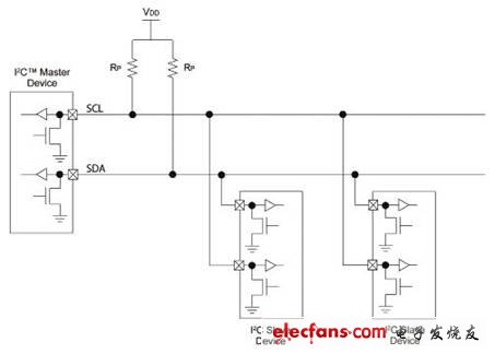
I2C is a two-wire synchronous bus, using the signal generated on the SCL line of the bus master as the clock. The SDA line is used for bidirectional data transmission. When the clock is in a specific state, the data lines can be modified to indicate the start and stop of the transmission, thereby avoiding the use of more lines. The I2C bus is based on the open collector output, where the device can pull the low line level through a grounded transistor, as shown in Figure 1. In this way, the bus control can be easily arbitrated to realize bidirectional communication and multi-master device support on one data line. As shown in Figure 1, each line has an external resistor connected to Vdd, which can pull the line high when the bus is released or the bus is idle.

Figure 1 I2C â„¢ bus topology
Three factors need to be considered when determining the pull-up resistance (Rp):
• Power supply voltage (Vdd)
• Total bus capacitance (CBUS)
• High level total input current (IIH)
Use the following conditions as an example to calculate the ideal pull-up resistor value:
• The power supply voltage (Vdd) is 5V
• Clock frequency is 400kHz
• Bus capacitance is 100pF
Power supply voltage (Vdd)
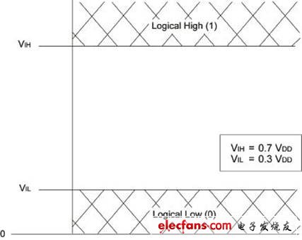
The I2C specification defines voltages lower than VIL or lower than 30% of the power supply voltage as logic low levels. Similarly, voltages higher than VIH or higher than 70% of the power supply voltage are defined as logic high levels, as shown in FIG. 2. The voltage between these two levels is an ambiguous logic level. In fact, the pin will read the level in this range as a logic high or logic low level, but it may be different between devices because temperature, voltage, noise sources, and other environmental factors affect the logic level.

Figure 2 Voltage levels designated as logic high and logic low
Advanced drives for fluid and gas handling applications with embedded energy monitoring, information management and process optimization.
Three Phase Inverter,Voltage To Frequency Converter,Frequency Note Converter,Industrial Automation Inverter
Wuxi Trenty Machinery & Equipment Co., Ltd. , https://www.elec-inverter.com