introduction
The cruise control system (CCS) was developed in the 1960s and is also called a constant speed driving system. When the cruise control system is working, the ECU judges the running status of the car according to the signals sent by various sensors, and automatically adjusts the opening of the throttle through the actuator to keep the running speed of the car consistent with the set speed. When the car is driving on a good road for a long time, the driver activates the cruise control system and sets the driving speed. The driver does not need to manipulate the accelerator pedal, and the cruise control system can automatically maintain the predetermined driving speed, which not only reduces the driver's labor Intensity, while using advanced electronic control technology to control the opening of the throttle valve, is more accurate than the driver's operation of the throttle valve, and the fuel economy and emission pollution of the car can also be improved.
1 System principle
1.1 Principle of electric control throttle
When working, the driver sends a speed control command, the throttle opening sensor collects the engine speed parameter, and inputs the signal to the electronic control unit; the electronic control unit compares the control signal with the feedback throttle position signal, according to the comparison The result is to drive the actuator to change the opening degree of the throttle valve, so that the actual opening degree and the control opening degree are consistent, so as to realize the automatic control of the vehicle speed.
1.2 Principle of servo control
The servo is a position (angle) servo drive, suitable for those systems whose angle needs to be constantly changing and can be maintained. S3003 servo has three pins, which are power supply Vcc, ground GND and control line Signal. The control signal enters the signal modulation chip from the Signal channel to obtain the DC bias voltage [2]. It has a reference circuit inside, generates a reference signal with a period of 20 ms and a width of 1 to 5 ms, compares the obtained DC bias voltage with the voltage of the potentiometer, and obtains a voltage difference output. Finally, the positive and negative of the voltage difference are output to the motor drive chip to determine the positive and negative rotation of the motor. When the motor speed is constant, the potentiometer is driven to rotate through the cascade reduction gear, so that the voltage difference is 0, and the motor stops rotating.
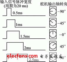
The input of the control line is a periodic square wave pulse signal with adjustable width. The period of the square wave pulse signal is 20 ms (that is, the frequency is 50 Hz). When the pulse width of the square wave changes, the angle of the servo changes, and the angle change is proportional to the pulse width. The relationship between the output shaft rotation angle and the input pulse width is shown in Figure 1.

Figure 1 The relationship between the output angle of the servo and the input pulse width
2 System design
This system uses Samsung's S3C2410 and Futaba's S3003 servos as controllers and actuators, respectively, using Linux operating system. The experimental platform is the engine experimental platform of Jinan Hengxin Co., Ltd.

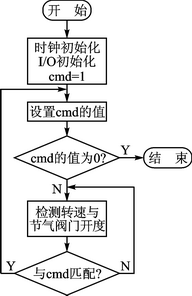
Figure 2 System flow
2.1 System design process
The system flow is shown in Figure 2. The controller S3C2410 completes various initialization tasks, receives cmd instructions from the operator, and performs a series of processing according to the value of cmd, including stopping the actuator and how many angles to rotate. Then the equivalent cmd value is calculated by the throttle opening sensor and the rotation speed sensor, and compared with the cmd to decide whether to make the next cmd judgment or adjust the angle of the actuator.
2.2 Set the Linux system clock frequency
In order to reduce electromagnetic interference and reduce wiring requirements between boards, the frequency of the crystal oscillator external to the chip is usually very low, and the system clock is improved by the PLL of the clock control logic [3]. Several recommended clock frequencies are listed in the Samsung S3C2410A manual. Here we choose the configuration of the output clock frequency FCLK = 202? 80 MHz, that is, in the PLL control register: MDIV = 161 (0xa1), PDIV = 3, SDIV = 1.
Set in UBoot's board / smdk2410 / smdk2410.c:
#define M_MDIV 0xA1
#define M_PDIV 0x3
#define M_SDIV 0x1
int board_init (void) {
...
/ * configure MPLL * /
clk_power? ﹥ MPLLCON = ((M_MDIV ﹤﹤ 12) + (M_PDIV ﹤﹤ 4) + M_SDIV);
...
}
Set the ratio of FCLK, HCLK and PCLK in cpu / arm920t / start.S of UBoot:
/ * FCLK: HCLK: PCLK = 4: 2: 1 * /
ldrr0, = CLKDIVN
mov r1, # 3
strr1, [r0]
It can be known from the above program that FCLK = 202.80 MHz, HCLK = 101-40 MHz, PCLK = 50.70 MHz, and the clock used by the PWM module of S3C2410 is PCLK, so the input clock of PWM is 50.7 MHz.
Wake up naturally in the morning sun, give you moisturizing company from morning to night, relax at home, and give you inseparable moisturizing. It is a good helper to relieve the pressure of dryness and water shortage, and the secret magic weapon to improve work efficiency.Delicate water particles can reach the bottom of the skin to be delicate and moisturizing, and the deep hydration makes the skin absorb water like a sponge.
Office Humidifier,Office Building Humidifier,Office Humidifier For Desk,Commercial Office Humidifier
Guangdong Aiyimi Electronic Technology Co., Ltd. , https://www.seventreasuresfan.com