Fault protection is an important feature of all power controllers. Almost all applications require overload protection. For peak current mode controllers, this can be easily accomplished by limiting the maximum peak current. In a discontinuous reverse configuration, setting a limit for the peak current can ultimately limit the power that the power supply draws from the input source. However, limiting the input power does not limit the output current of the power supply. If the input power remains the same in the event of an overload fault, the output current increases as the output voltage drops (P = V * I). In the event of a short circuit fault, this can cause unacceptably high losses in the output rectifier or system power distribution. This article uses some small innovations and several additional components to show you how to improve a simple peak current limit, turning the power supply into a constant current source instead of a constant power source.
Figure 1 compares the ideal output voltage with a constant power and constant current limit current. In both cases, the overload fault protection works at 120% of the maximum rated load. In a system that uses power limiting, the output current increases as the load increases in reverse voltage. In real-world systems, a power-limited reverse controller will turn off at some point due to the controller's bias loss. In contrast, once the overload threshold is exceeded, the system with current limiting will shut down immediately. Current limiting can be achieved by directly detecting the load current on the secondary side of the isolation boundary. However, doing so requires more circuitry, less efficiency, and the cost is generally prohibitively high.

Figure 1 The ideal power limit produces a strong current that triggers fault protection.
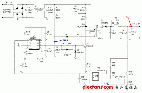
Figure 2 shows a schematic of a 5V/5W non-continuous reverse power supply used by a mobile device charger. In the example, we used the UCC28C44 controller, which is representative of most economical peak current mode controllers with power limiting. In a discontinuous reverse structure, if the efficiency effect is ignored, Equation 1 can be used to calculate the magnitude of the load power (P).
![]() Equation 1
Equation 1
Since the transformer inductance (L) and the switching frequency (f) are fixed, the output voltage (VOUT) can be adjusted by controlling the peak primary current (IPK). As the output current (IOUT) increases, the voltage begins to drop, but the feedback loop requires a higher peak current to maintain voltage regulation.

Figure 2 This 5V/5W reverse achieves power limitation by limiting peak transformer current.
Inside the inverter, the feedback voltage at pin 1 (COMP) is compared to the peak current. This peak current is detected by R15 and filtered using R13 and C12. If the current sense voltage reaches 1V, the individual overcurrent comparator terminates the pulse. This peak current limiting method is the same as the power limiting process in most pulse width modulation (PWM) controllers. Equation 1 can be rewritten as Equation 2 if the power remains constant. In this equation, we can clearly see that the output current is inversely proportional to the output voltage when the power is limited.
 Equation 2
Some controllers also include a second stage comparator. When the peak current is higher than the first stage comparator, the second stage comparator trips open. This second stage comparator triggers the controller to shut down completely and initiates a restart cycle. The purpose of this additional protection stage is to prevent catastrophic failure of the power supply itself, such as shorting the transformer windings or shorting the output diodes. However, most situations involving short-circuit loads generally do not exceed this threshold.
The control switch is a special switch for process control of electrical control and thermal instrumentation. Specifically, there are positioning operation, self-resetting operation, positioning-self-resetting operation, blocking operation, positioning-blocking operation, self-resetting-positioning-locking operation and so on.
The types of Control Switches are:
ME Limit Switch
Micro Switch
QS5 Cam Switch
Universal Changeover Switch
Foot Switch
Proximity Switch (Sensors)
Switching Power Supply Unit
Float Switch
Weather Proof Isolating Switch
Isolating Switch and Changeover Switch
Control Switches
Control Switches,Float Switch,Proximity Switch,Cam Switch
Ningbo Bond Industrial Electric Co., Ltd. , https://www.bondelectro.com