introduction
In the late 1960s, Hewlett-Packard designed the so-called HP-IB (Hewlett-Packard Interface Bus) as a communication channel between independent instruments and computers. Because of its high-speed data transmission rate (at that time), it was quickly accepted by everyone, so later IEEE renamed this interface to GPIB (General Purpose Interface Bus). However, in order to cope with more complex test environments and challenges, GPIB appears to be stretched. The VXI Association was established in 1987, and the so-called instrument-on-a-card standard was established, which is VXI (VMEbus eXtensions for InstrumentaTIon). VXI's modular and rugged architecture does bring many benefits to the measurement and automation industry.
In the past ten years, with the dramatic revolution and popularization of personal computers, instrument modules based on PCI Bus have greatly developed. Therefore, the PXI System Alliance (PXISA) was established in 1998, making PXI (PCI eXtensions for InstrumentaTIon) an open standard architecture. The PXI platform not only has an open architecture similar to VXI and a rugged mechanism, but also because it designs a series of synchronization signals suitable for instrument development, it makes PXI more suitable as a platform for measurement and test, and control automation.
1 Introduction to PXI
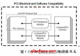
In simple terms, PXI is a framework based on PCI (Peripheral Component Interconnect) and CompactPCI plus some PXI-specific signals. PXI inherits the electrical signals of PCI, so that PXI has a very high data transmission capability like PCI bus, so it can have a transmission performance of up to 132Mbyte / s to 528Mbyte / s, which is fully compatible in software. On the other hand, PXI adopts the same mechanical appearance structure as CompactPCI, so it can also enjoy the characteristics of high density, rugged housing and high-performance connectors. The relationship between PXI and CompactPCI is shown in Figure 1.

1.1 Internal structure of PXI system
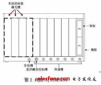
A PXI system consists of several components, including a chassis, a PXI backplane (backplane), a system controller (System controller module), and several peripheral modules (Peripheral modules). Take an eight-slot PXI system with a height of 3U as an example, as shown in Figure 2. The system controller, that is, the CPU module, is located in the first slot on the left side of the chassis. Three expansion slots are reserved on the left side for the system controller to insert a system card with a large volume due to complex functions. Starting from the second slot to the eighth slot is called a peripheral slot, which allows users to plug in different instrument modules according to their own needs. The second slot can also be called Star Trigger Controller Slot.

1.2 PXI-specific signals
The P1 connector on the back panel has 32-bit PCI signals, and the P2 connector has 64-bit PCI signals and PXI special signals. So what are the signals unique to PXI? The signals of PXI include the following, and its complete architecture is shown in Figure 3.

1.2.1 10MHz reference clock (10MHz reference clock)
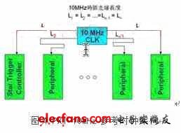
The PXI specification defines a low skew 10MHz reference clock. This reference clock is located on the backplane and is distributed to each peripheral slot. Its feature is that the wiring length from the clock source to each slot is the same length, so each peripheral The clocks received by the slots are all in the same phase, which is a convenient clock source for the synchronization of multiple instrument modules. The basic 10MHz reference clock architecture is shown in Figure 4.

mini usb flash drive 256gb,Clip Usb Stick With Logo,Mini Usb Keys With Keychain,Mini USB flash disk,mini usb flash drive 16gb
Shenzhen Konchang Electronic Technology Co.,Ltd , https://www.konchang.com