In this paper, starting from the analysis of the physical structure of the combined electro-magnetic antenna, combined with experiments and numerical simulations, a combination of frequency and time domain measurements is used to study the characteristics of the combined electro-magnetic antenna.
1 Theoretical analysis
1.1 Antenna structure
Figure 1 is a schematic diagram of the structure of the combined electro-magnetic vibrator ultra-wideband antenna [2]. As shown in the figure: ①is the coaxial feed area of ​​the antenna; ② is the outer conductor plate; ③ is the current loop regulator; ④ is the upper plate of the TEM horn; ⑤ is the lower plate of the TEM horn.
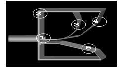
Figure 1 Schematic diagram of the combination of electro-magnetic vibrator UWB antenna
1.2 Analysis of the physical structure and characteristics of the antenna
The physical structure of the antenna is closely related to the antenna performance. The mismatch between the input impedance of the radiating antenna and the characteristic impedance of the ultra-wide spectrum pulse source causes reflections at the antenna feed to varying degrees. From the perspective of the antenna structure shown in Figure 1, after the excitation pulse (as shown in Figure 2) enters the coaxial feed zone, a pulse current with a wide frequency band characteristic (as shown in Figure 3) is fed into the antenna. A part of the current is radiated to the free space through the current loop (or magnetic vibrator) formed by ①, ③, and ②, and simultaneously generates reflected waves and heat consumption (due to the lower upper frequency of the excitation pulse, the heat loss of the antenna is generally not considered); Part of the current is radiated to free space through the impedance gradient TEM horn (mainly expressed as an electric vibrator radiator) composed of ①, ④, and ⑤, and also generates reflected waves.

Fig.2 Excitation pulse waveformFig.3 Excitation pulse spectrum
According to the above analysis, the equivalent circuit of the antenna can be obtained, as shown in FIG. 4. Among them, Rring and Rtrumpet are the radiation resistance of the antenna's magnetic oscillator (current ring) and electric oscillator (TEM horn), respectively, and they have a nonlinear relationship with the frequency f of the excitation signal.

Figure 4 The equivalent circuit diagram of the electro-magnetic vibrator antenna
The current loop in the antenna is a parallel resonant circuit. As the frequency increases, the current loop gradually changes from a low-frequency short-circuit load to a radiator mainly dominated by a magnetic vibrator, and the radiation resistance Rring of the magnetic vibrator increases accordingly. For low frequencies, the current ring is a small ring radiator, which is equivalent to a magnetic basic vibrator, and its radiation characteristics are equivalent to the magnetic basic vibrator; while for high frequencies, it is equivalent to a large current ring radiator, which can be applied to a large current ring. Radiation theory to analyze its input characteristics and radiation characteristics.
In the combined electro-magnetic vibrator ultra-wideband antenna, the TEM horn is equivalent to a series resonant circuit. As the frequency increases, the TEM horn gradually changes from a low-frequency open-circuit load to a radiator dominated by an electric vibrator, and the radiation resistance Rtrumpet of the electric vibrator also changes accordingly. For low frequencies, the most basic physical model of a TEM horn is a dipole antenna, whose radiation field is a vector superposition of several dipole fields. The expression of the time-domain radiation field [4] is:

Where: f (g) is the ratio of the characteristic impedance of the TEM horn to the free space impedance, δ (a) (t) is the impact function, h is the height of the horn mouth, l is the length of the horn, and V0 is the step voltage fed into the antenna The amplitude.
As the frequency is further increased, the TEM horn is transformed into a high-frequency short-circuit load. When the frequency f is very high, the electric oscillator of the TEM horn and the magnetic oscillator of the current ring are both seriously detuned, and are in short-circuit and open-circuit states, respectively. Causes greater reflection at the feed.
In the combined ultra-wideband antenna of the electro-magnetic vibrator, the far-field radiation field of the electric vibrator and the magnetic vibrator are both vertically polarized waves. By adjusting the parameters Lring, Ctrumpet and the phase center distance between the magnetic oscillator and the electric oscillator, the two antenna oscillators form complementary electro-magnetic oscillator radiation [3], thereby reducing the dependence of the antenna's radiation resistance on the signal frequency and expanding the antenna's work The frequency band reduces the reflection caused by the mismatch of the antenna load, and also enables the spatial transient radiation fields of the two radiators to be superimposed on each other, maximizing the radiation efficiency of the antenna.
2 Simulation calculation
On the basis of the above analysis, the 50x50x50cm3 combined electro-magnetic vibrator ultra-wideband antenna was simulated using numerical simulation software. Figures 5 and 6 show the results of numerical simulation.

(a) Antenna standing wave curve (b) Antenna input impedance pie chart
Figure 5 Simulation results of 50cm electro-magnetic vibrator combined antenna
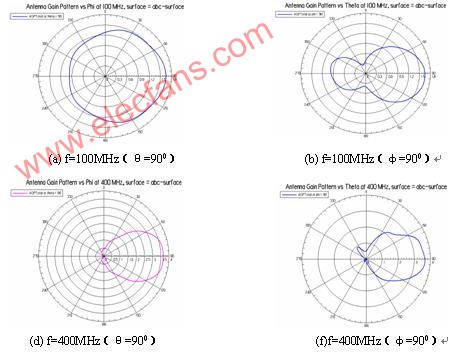
Fig.6 Directional diagrams of the 50cm electro-magnetic vibrator combined UWB antenna at θ = 900 and φ = 900 planes at different frequencies
3 Experimental results
Through simulation and analysis, a set of combined electro-magnetic vibrator UWB antennas with a length, width and height of 50 cm (as shown in Figure 7) was optimized, and the antennas were measured by frequency and time domain measurement methods
test.
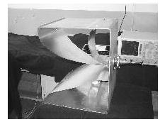
Fig. 8 is the antenna standing wave curve, impedance circle graph and time domain reflection measurement curve measured by Anritsu's loss-of-network analyzer MS4623B. The frequency domain measurement results show that the antenna's standing wave coefficient is less than 3 in the 10 octave range from 100MHz to 1GHz, which is basically consistent with the numerical simulation results. From the time domain measurement curve Figure 8 (c), it can be seen that the antenna has the largest reflection point at the feed output end of the combined electro-magnetic vibrator UWB antenna.
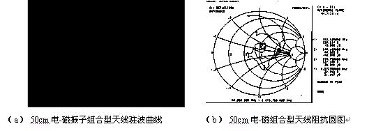
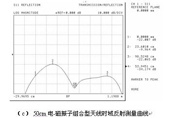
Figure 8 MS4623B out-of-network measurement results
Figure 9 shows the incident pulse, reflected pulse and radiated field pulse waveforms measured by Tek TDS684 when the antenna is fed with ultra-wideband pulse signals. Among them, the bottom width of the excitation pulse signal is about 2ns, the leading edge is 350ps, and the peak voltage is 150V. The incident signal and the reflected signal use a non-inductive capacitive voltage divider (the voltage division ratio is 100: 1). The measurement of the radiation field uses a TEM horn with a bandwidth of 80MHz ~ 2GHz and an effective height of 6.1cm. 10m away from the mouth. The maximum positive peak of the reflected wave is 29.8V, the maximum negative peak is -35.6V, and the electric field intensity at the measuring point is 24.6V / m. Obtain the antenna radiation efficiency Kw = Wr / Wg = 60% (Wr = Wg-Wref is the radiant energy of the antenna, Wg is the excitation pulse energy, and Wref is the antenna reflected pulse energy).

Figure 9 Time domain measurement waveform
4 Conclusion and existing problems
Through the above analysis and research, it is concluded that the combined electro-magnetic vibrator antenna uses the complementary state of the current loop and the TEM horn to achieve bandwidth expansion, the antenna structure parameters are adjusted properly, and the miniaturized UWB antenna can achieve wide bandwidth and high radiation efficiency; The antenna has a small size. Due to the coaxial transition feed structure, it can solve the problem of high-power UWB pulse feeding. The antenna structure and transient pulse radiation problems are more complicated. It is not suitable to directly and completely adopt the time domain method, but the frequency domain method. It is relatively easy to study the structure and characteristics of the antenna, which creates conditions for the study of the antenna's time-domain characteristics.
The existing problem is: due to the complexity of the antenna structure, it is quite difficult to solve the current distribution of each part of the antenna. In addition, when performing the simulation calculation of the combined electro-magnetic vibrator antenna, due to the limitation of computing resources and the relationship between the model and the actual antenna There is a large difference, which causes an error between the calculation and the measurement result.
Automotive Fug Wire Tap,Fuse Tap Adapter,Cor Add A Circuit Fuse Tap,Inline Fuse Holder
Dongguan Andu Electronic Co., Ltd. , https://www.idofuseholder.com