Having good car taillight performance is essential for cars and an important part of driving safety. The flashing of car taillights is not irregular (electric vehicle controller), it is constantly changing according to the direction of the car. The automobile tail light control circuit (automobile control system) is closely related to the changes of the automobile tail light. In short, the automobile tail light control circuit controls the change law of the automobile tail light. Then the working principle of the automobile tail light control circuit and how is it designed? The author summarizes the relevant knowledge of the automobile tail light control circuit (automotive electronic control technology) by collecting and collating data as follows.
The working principle of the control circuit of the automobile tail light
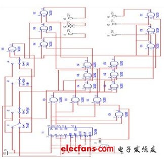
The automobile tail light control circuit includes a decoding circuit and a display driving circuit. The display driving circuit is composed of 6 light emitting diodes and 6 inverters (7404); the decoding circuit is composed of 3-8 line decoders 74138 and 6 NAND gates (7400). The three input terminals A, B, and C of the 74138 are connected to the output terminals 1Q, 2Q and the steering control switch of the ternary counter [2]. When [2] = 0, the enable terminal signal G = 0 (the decoder works), S = 1, and the state of the counter is 00, 01, 10, the corresponding output terminals Y0, Y1, Y2 of 74138 are "0" "Effective, that is, the output terminals of the inverters G1 to G3 are also sequentially 0, so the indicator lights in the order of D3 ↠D2 ↠D1. If the above conditions remain unchanged, and [2] = 1, the output terminals Y4, Y5, and Y6 corresponding to 74138 are 0 in order, that is, the outputs of inverters G4 to G6 are 0 in sequence, so the indicator light is D4 → D5 → D6 lights sequentially. When G = 1 (the decoder prohibits decoding) and S = 1, the output of 74138 is all 1, the outputs of G1 ~ G6 are all 1, the indicator lights are all off; when G = 1, S = CP, it indicates The light flashes with the frequency of CP. ("1" means high level, "0" means low level), the current-limiting resistance in the circuit is 0.2 kΩ. The automobile taillight control circuit is shown in the figure.

Car rear light control circuit diagram
This circuit uses several cheap transistors and two relays to make the bus's twitch signal and turn signal can comprehensively control the tail lights; both tail lights are on when braking, and only one tail light is on when turning. The turn signal causes the tail light to turn on twice per second. When turning, C1 and C2 charge to the peak pressure of the turning signal. The size of the capacitor should be such that the relay can pull in and out during the interval between lamp flashes. If the capacitor is selected too large, the brake signal will not illuminate the tail light immediately after the turn signal is removed. This circuit is designed for a new type of car. In order to ensure safety, this kind of car needs to separate the turn signal and the brake signal.
Design scheme of automobile tail lamp control circuit
There are three lights on the left and right sides of the rear of the car. When turning left, turning right, braking and checking, the indicator light flashes according to the specified requirements.
The design requirements of the automobile tail light control circuit are: suppose that there are three indicator lights on the left and right sides of the automobile tail (simulated with light-emitting diodes).
(1) The indicator lights are off when the car is running normally;
(2) When turning right, the three indicators on the right light up in the order of the right cycle;
(3) When turning left, the three indicators on the left light up in the order of the left cycle;
(4) During temporary braking, all indicators flash simultaneously [2]. Use three switches to control the lighting status of the indicator.
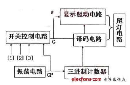
According to the design requirements, draw a block diagram of the automotive tail light control circuit, as shown.

Functional block diagram of automobile tail light control circuit
According to the design requirements, this automobile tail light control circuit is composed of an oscillation circuit, a ternary counter, a decoding circuit, a display driving circuit, and a switch control circuit. As the car turns left and right, the three indicator lights circulate, so the ternary counter is used to control the decoder circuit to output low level in sequence, so as to control the tail light to light up as required.
Rubber cable is also rubber sheathed cable. As its name implies, it is a wire and cable with various rubbers or thermosetting elastomers with equivalent performance as the insulation and sheath foundation.
Because of its unique flexibility, rubber sheathed cables are very suitable for use in indoor and outdoor environments, including wet and even water conditions. They are usually used on mobile electrical equipment. They are suitable for electrical and pneumatic connection or wiring with AC rated voltage of 300V/500V and 450V/750V below.
Rubber sheathed cables are used by products in many fields due to their unique mechanical and physical properties, so they are classified into many categories, such as mobile universal rubber sheathed cables, electric welding machines, electric power, marine, mining, wind energy, nuclear energy, etc., among which mobile universal rubber sheathed cables and mining cables are widely used.
Advantages
1. Good water resistance, less air permeability.2. It can be mixed with other rubber or plastics to improve the performance of rubber.
3. Good heat resistance. The heat resistance of rubber is better than that of natural rubber and styrene butadiene rubber.
4. The physical and mechanical properties are average. The mechanical properties of rubber without reinforcing agent are poor.
5. It has excellent oil resistance and solvent resistance. The higher the content of acrylonitrile, the better the oil resistance.
Rubber Cable,Rubber Welding Cable,Outdoor Copper Wire Rubber Cable,Flexible Rubber Sheathed Cable
Ruitian Cable CO.,LTD. , https://www.hbruitiancable.com