Key words: laser communication; laser drive; photoelectric detection; underwater network
CLC number: TN929.1
Document identification code: A
DOI: 10.16157/j.issn.0258-7998.170371
Chinese citation format: Zhang Jun, Cai Wenyu, Wen Duanqiang. Research on underwater high-speed laser communication system and networking technology[J].Application of Electronic Technique, 2017, 43(9): 53-56, 60.
English Reference Format: Zhang Jun, Cai Wenyu, Wen Duanqian. Research on technology of underwater high speed laser communication system and networking [J]. Application of Electronic Technique, 2017, 43 (9): 53-56, 60.
0 Preface
Underwater acoustic technology is one of the most mature underwater communication technologies, but the transmission rate of sound waves in water is extremely low, less than one-twentieth of the speed of light, and the power consumption is large. It is difficult to carry water on underwater robots. Under data communication. Optical communication technology can overcome the disadvantages of narrow underwater acoustic communication bandwidth, large environmental impact, low applicable carrier frequency and large transmission delay. Therefore, in some application scenarios, underwater optical communication can replace underwater acoustic communication. High transmission rate, high bandwidth, medium and short range communication requirements. Underwater optical communication can be divided into LED optical communication and laser communication. LED as a light source has the disadvantages of large divergence angle and short transmission distance [1], so laser is more suitable as underwater light communication light source. Moreover, providing reliable communication methods for underwater sensor networking has also become an application scenario for optical communication. In the sensor nodes in the short to medium range, underwater optical communication can provide a high-speed, low-cost, high-stability communication method for inter-node communication. Underwater communication can be used as a communication method between nodes in the long-distance range, which is a supplement to the communication mode between nodes, so as to better realize the wireless networking of underwater multi-sensor [1].
1 System working principle
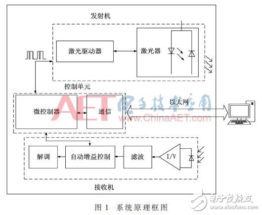
This paper proposes a underwater medium-to-small-distance wireless communication scheme based on laser communication. The overall design framework is shown in Figure 1. It is mainly composed of power supply, control unit, transmitter and receiver. The control unit is mainly used for controlling the peripheral module and performing Ethernet-based data interaction with an external PC; the transmitter is mainly used to load the excitation signal to the laser to generate a corresponding optical signal; the receiver mainly realizes receiving The incoming optical signal is converted into an electrical signal, and the signal is processed correspondingly, and the automatic control of the gain is realized at the same time, and the influence of the change of the optical signal strength on the circuit is reduced.
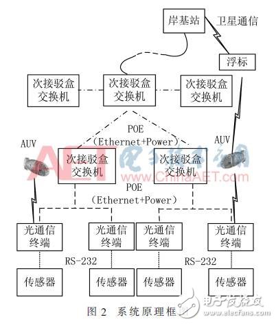
Aiming at the application scenarios of underwater sensor networking, this paper proposes a underwater communication networking system based on laser communication, as shown in Figure 2. Each laser communication terminal is connected to various types of sensors on the sensor network via an RS-232 bus. All laser communication terminals in each area are connected to the secondary switch box through POE (Power Over Ethernet) [3], and the maximum power of the POE power supply reaches 12.95 W. In addition, the secondary box switch that manages multiple areas is controlled by a main box switch, and the main box switch converts the network signal into a fiber signal through the fiber module and transmits it to the shore base station. In addition to this, the sensor data transmitted by the laser communication terminal device to which the required area sensor is connected is collected by the underwater movement process of the AUV equipped with the optical communication system. Subsequently, the AUV sends the data to the buoy relay on the sea through various communication methods, and transmits the data to the shore base station through satellite communication.
2 system hardware design
2.1 Transmitting circuit design
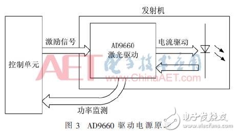
The laser is a sensitive light source device. The stability of the input current directly affects the working life of the laser. The large ripple or large current of the burr will directly lead to the safe use of the device or even damage the device. The voltage source driver circuit cannot provide a stable current, so the laser driver circuit should use the current source drive mode. This system uses AD9660 chip of Analog Devices as the laser driver chip. The AD9660 features a maximum bias current of 120 mA, a modulation current of 180 mA, an ultra-low rise/fall time of 1.5 ns/2 ns, a modulation frequency of up to 200 MHz, and an efficient optical power control loop. The principle of the AD9660 driver circuit is shown in Figure 3.
2.2 Receiver circuit design
The receiving circuit mainly includes a photoelectric conversion circuit, a low-pass filter circuit, and an automatic gain control circuit. The photoelectric conversion circuit is responsible for converting the weak current signal of the photodiode into a voltage signal, and the low-pass filter circuit filters the interference noise while amplifying the weak voltage signal, and the automatic gain control circuit controls the filtered signal to a controllable amplitude. value.
2.2.1 photoelectric conversion circuit
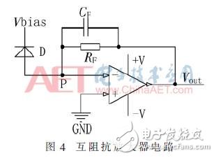
The output signal of the photodiode is a current signal, and the current-voltage conversion is implemented using a transimpedance amplifier circuit. The optical power monitoring of the laser driver chip can obtain the intensity of the light, so the selection of the transimpedance amplifier is high. The main requirements include high input impedance, large bandwidth, high slew rate, low noise, and excellent frequency response. This system selects TI OPA657 transconductance amplifier as the core device of photoelectric conversion circuit, and the transimpedance amplifier circuit is shown in Figure 4.
2.2.2 photoelectric conversion circuit
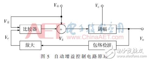
The core of the automatic gain control circuit consists of the voltage controlled amplifier VCA810, the operational amplifier OPA820, and the D/A output of the microcontroller. The VCA810 is a wideband, voltage-controlled amplifier that supports single-ended and differential inputs with gain control linearly varying from -40 dB to 40 dB. The OPA820 is a unity-gain stable low noise voltage feedback operational amplifier. The principle of the automatic gain control circuit is shown in Figure 5. By controlling the D/A output, the output of the automatic gain circuit is controlled at Vpp of about 1 V.
2.3 Demodulation circuit design
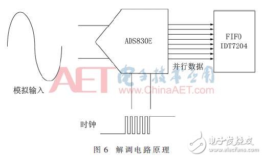
The core of the demodulation circuit is composed of a high-speed parallel A/D conversion chip ADS830E and a FIFO chip IDT7204. The principle is shown in FIG. 6. The sampling clock of the A/D chip is provided by a 30 MHz active crystal oscillator. The waveform generated by the crystal oscillator is shaped by a gate circuit composed of 74HC08 to obtain a stable clock signal. The input analog voltage range of the ADS830E chip is 1.5 V to 3.5 V. Therefore, the input voltage needs to be biased to 2 V, which is obtained by the resistor divider of the AVT830E's REFT and REFB. At the same time, the input signal is controlled by the automatic gain control circuit to within 1.5 V, so as not to exceed the safe input range, resulting in damage to the A/D chip. The input signal of the ADS830E is the output signal of the voltage follower composed of OPA691.
3 system software design
3.1 Overall design of the software
The embedded software part of the system includes the main program, which mainly implements system initialization, LwIP protocol stack, initialization of various peripheral modules and coordination of control systems. The laser drive control program mainly drives the laser driver chip, and loads the modulation signal onto the laser to realize electricity. The signal-to-optical signal conversion; the automatic gain control program dynamically adjusts the circuit gain through the feedback loop to realize the adaptive function; the demodulated data reading program mainly realizes the data outputted by the demodulation circuit saved in the FIFO buffer IDT7204. At the same time, it is necessary to ensure that the data is not lost and not covered; the network data transmission program mainly implements data interaction between the Ethernet server and the underwater system.
3.2 Software Design
The laser driver code mainly relies on the control of the microcontroller I/O according to the operation timing of the AD9660, thus implementing functions such as laser driving and automatic power control. The driver code of the AD9660 mainly involves the initialization of the corresponding GPIO port of the microcontroller, the establishment of the configuration loop, and the establishment of the write current loop.
The specific operation process is as follows:
(1) Enable the AD9660 chip, that is, set the DISABLLE pin to “0â€;
(2) Open and establish a bias loop, that is, set the BIAS CAL pin to "1" and then set it to "0";
(3) Open and establish a modulation loop, that is, set the WRITE CAL and WRITE PULSE pins to "1";
(4) The modulation signal is loaded onto the laser diode, that is, the high and low level corresponding to the modulation signal is correspondingly set to WRITE CAL and WRITE CAL pin "1" or "0";
(5) periodically re-establishing the bias loop;
(6) Disable the AD9660 when not in use, ie set the DISABLE pin to "1".
3.3 Ethernet software design
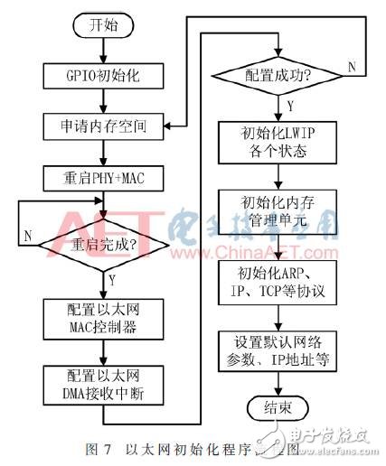
The Ethernet protocol LwIP protocol stack [4] modifies the underlying code for the configuration of the PHY chip to support the related configuration operations of the DP83848. The controller Ethernet DMA data receive interrupt is then turned on, allowing the microcontroller to save the received temporary data. After the hardware drivers are configured, the LwIP kernel is initialized, and then the relevant functions of the application are run to perform data transmission and reception. The program flow is shown in Figure 7.
3.4 Network Protocol Design
The packet types designed in this paper mainly include data packets, control packets, and status packets. The message is mainly composed of the primary node serial number, the secondary node serial number, the packet type, and the data segment.
The serial number is mainly to distinguish the data sent by different nodes. The protocol assigns a unique node number to each sensor node under water. The node number consists of the primary node number and the secondary node number. The master node number represents the sensor area. The secondary node switch is an area. The master node number starts from 1. Each time a secondary box switch is added, the master node number is incremented by 1. The secondary node number represents the sensor connected under a secondary switch box switch. The secondary node number starts from 1. Each time a sensor is added, the secondary node number is incremented by 1. The primary and secondary nodes sent by the AUV to the optical communication terminal are all 0. . The allocation method of the primary and secondary node numbers can better classify the data, preferentially retrieve the primary serial number, and then retrieve the secondary serial number according to the primary serial number. Based on the above networking protocol, the connection process of the AUV and the optical communication terminal connected to the sensor node is as shown in FIG. 8.

4 comprehensive debugging
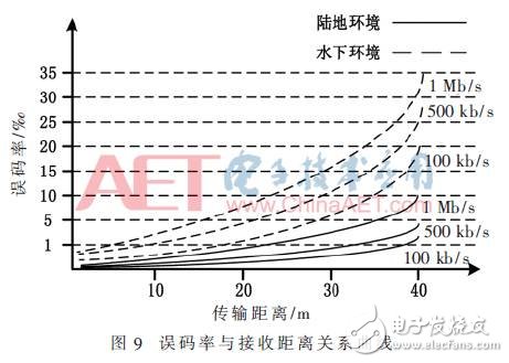
The communication test consists of a terrestrial test and an underwater test. The communication is from 1 m to 40 m, and the transmission error rate is tested every 2 mm. The relationship between the bit error rate and the receiving distance is shown in Fig. 9, where the real curve represents the terrestrial environment and the dashed curve represents the underwater environment. The horizontal comparison shows that under the same environment, as the transmission distance increases, the bit error rate also increases. Vertical comparison shows that the bit error rate of the terrestrial environment is better than that of the underwater environment under the same distance of different environments; Under the same distance of the environment, as the transmission rate increases, the bit error rate also increases.
5 Summary
This paper designs and develops a set of underwater high-speed blue-green laser communication system, and provides a networking solution for underwater sensor observation network. The system hardware and software design and its implementation method are proposed. Finally, a small-volume, low-power, high-rate laser communication system is developed, which overcomes the shortcomings of traditional acoustic communication and provides a kind of underwater sensor observation network. Effective networking.
CAT6 rj45 Keystone Jack is a part of networking cabling solutions for patch panels, wall mounting plates,face plates, surface mount boxes with T568A T568B standard wiring. It could get 10G+ Ethernet calbing solutions with more conveniet, low price and cost effective in various packing customized.
The contacting point is finished by gold plated, and easy snap into retaining clip to make sure corrosion connecting freely and security.
CAT6 Keystone Jack,Keystone Jack CAT6,Cat6 keystone,cat6 keystone coupler
NINGBO UONICORE ELECTRONICS CO., LTD , https://www.uniconmelectronics.com