2. AC work grounding Connect a certain point in the power system directly or via special equipment with the earth as a metal connection.
The working ground mainly refers to the transformer neutral or neutral (N line) grounding. N-line must use copper insulated wire. There is an auxiliary equipotential connection terminal in the distribution, and the equipotential connection terminals are generally in the cabinet. It must be noted that this terminal block must not be exposed; it must not be mixed with other grounding systems such as DC grounding, shielded grounding, anti-static grounding, etc.; it must not be connected to PE lines.
3. Safety Protection Grounding Safety grounding is to make a good metal connection between the uncharged metal part of the electrical equipment and the grounding body. The electricity equipment in the building and some metal components near the equipment are connected with PE wires, but the PE wire and N wire are strictly prohibited.
1 Metal bases and enclosures for motors, transformers, lighting fixtures, hand-held or portable electrical appliances and other electrical appliances;
2 electrical equipment transmission;
3 Frames for the distribution, control and protection of discs (tables, boxes);
4 The structure of AC/DC power cables, the metal shell of the junction box and the terminal box, the metal sheath of the cable, and the threaded steel pipe;
5 metal structures of the interior and exterior switchgears or reinforcing bars of reinforced concrete structures and metal shields and metal doors close to live parts;
6 Overhead lines of steel towers or steel reinforced concrete towers and overhead lines on the towers, shells and supports of equipment mounted on the towers;
7 change (distribution) electrical base of various electrical equipment or bracket;
8 The metal housing of civilian appliances, such as washing machines, refrigerators, etc.
4, DC grounding.
In order to make the accuracy and stability of each electronic device high, in addition to a stable power supply, it must also have a stable reference potential. A large cross-sectional area of ​​the insulated copper core wire may be used as the lead, one end directly connected to the reference potential, and the other end for the DC grounding of the electronic device.
5. Shield grounding and anti-static grounding Grounding to prevent the static electricity generated by the dry environment of the electronic computer room in a building from causing interference to electronic equipment is called anti-static grounding. In order to prevent external electromagnetic field interference, the grounding of shielded wires or metal tubes worn inside and outside of the electronic equipment and the equipment is called shield grounding.
6, power grounding system electronic equipment, in order to prevent the interference voltage of various frequencies through the AC and DC power line intrusion, affect the work of low-level signal and equipped with AC and DC filters, filter grounding said power ground 7, repeated grounding In the TN-C system of the low-voltage power distribution system, in order to prevent loss of grounding protection due to a neutral line failure, resulting in electric shock hazards and damage to the equipment, the neutral line is repeatedly grounded. Repeated ground points in the TN-C system are:
1 The appropriate point of the terminal and the line of the overhead line;
2 Neutral cable of four-core cable;
3 The incoming line of a cable or overhead line at a building or a workshop;
4 The neutral line in a large workshop should be arranged in a circular arrangement and be grounded in multiple points;
Fiber optic systems include fiber optic terminal box, fiber optical Patch Panel, connectors, PLC splitter, Pigtail Patch cords, cable assemblies, accessories for both single mode and multimode applications. Together, these components provide complete solutions for today`s high data rate Fibre Channel and Ethernet applications, and support future readiness for 40 Gb/s and 100 Gb/s data rates, maximizing physical infrastructure performance, modularity, and scalability.

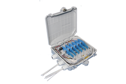
The Fiber Optic Terminal Box is designed for optical ber cable termination. It allows FO cable termination by splicing pigtails, and passive optical splitters 1:8 and installation. The ruggedized box is designed for both indoor and outdoor applications. The MOPF includes a holder for SC type coupling adapters and a splice cassette for heat shrinkable or mechanical splice protection sleeves and two separate holders for passive splitters. A weatherproof lock is provided. Provision for up to 2 optical ber cables to enter and 8 smaller entries to leave the enclosure through weatherproof cable glands is provided. The outlet ports allow installation of 8 connectorized patchords. Additionally, one universal cable output port is included.
Wall mountable
Easy access to cables, pigtails and patchcords during installation, maintenance and/or upgrade Secure, industry standard high impact plastic cover
Anti-UV, Ultra violet resistant
Protection class IP 65
Minimum value of bend radius is 30 mm
Can house 40-60 mm splice protectors
Can house 1x8 PLC splitters
2 inlet ports, 4/8/16/32/64 + 1 outlet ports
Fiber Optic System,Fiber Optic Cable,Fiber Optic Internet,Multimode Fiber
DOWELL INDUSTRY GROUP LIMITED , http://www.dropwirechina.com