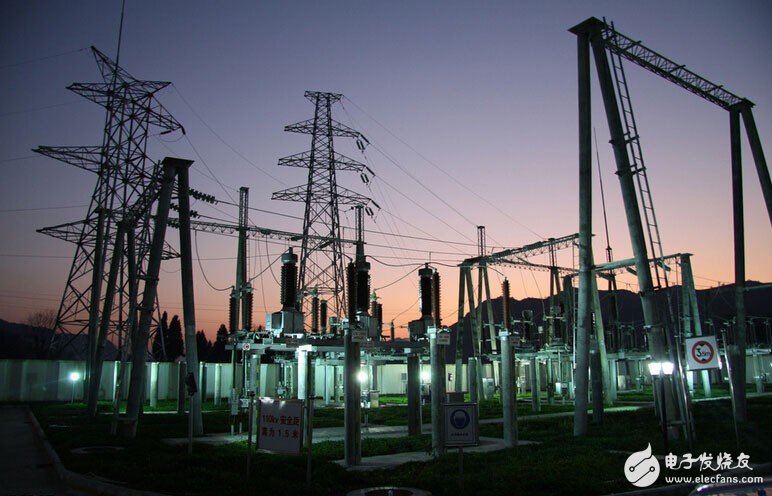
The wireless monitoring system of the unattended machine room in the power industry is mainly the operating state of the equipment room (such as power supply and distribution system, UPS power supply, air conditioning, fire protection system, security access control system, etc.), and the environmental dynamic state of the equipment operation (environmental temperature and humidity, smoke). Alarms, flooding alarms, etc., real-time monitoring and recording of historical data, realizing remote remote management functions of the power equipment room, enabling the power industry equipment room monitoring to be unmanned or under-managed, providing a powerful guarantee for efficient management and safe operation of the equipment room.
In order to make the linkage between devices normal and effective, different network transmission methods must be carried out for different environments. The composition of each system of the power plant and the layout of the network transmission are introduced here.

Transmission network system layout
1, the backbone transmission network
At present, the substation video data transmission to the monitoring and dispatching center mainly has the following transmission modes:
(1) Ethernet transmission method
The channel from each substation to the monitoring center is directly an Ethernet interface, and the optical fiber or microwave wireless network transmission device directly provides an Ethernet interface. The image data signals of each substation are uploaded to the monitoring center through various switches and routers.
The microwave wireless network transmission equipment generally adopts a high-bandwidth and long-distance 11N series outdoor wireless bridge (WB5800MN1, WB5800MN2), and adopts a point-to-point networking mode to ensure the overall link is smooth.
(2) 2M-Ethernet transmission mode
The channel from each substation to the monitoring center is 2M dedicated line. The communication equipment only provides 2M interface. The image data signal of the substation needs to be converted into 2M interface through 2M Ethernet bridge. The corresponding 2M Ethernet bridge uploaded to the monitoring center is converted into network signal and enters. The network of the monitoring center. In fact, it is equivalent to using a 2M Ethernet bridge to pass 2M dedicated line networking.
2. Transmission network in substation
In the outdoor field of the substation, 2.4G or 5.8G outdoor wireless bridges can be adopted according to actual needs, and point-to-point or point-to-multipoint networking mode can be adopted to wirelessly connect important places such as main transformers and gates that need to be monitored.
3, front-end video capture back
At each monitoring point, depending on the distance, a 2.4G or 5.8G built-in antenna integrated outdoor wireless bridge or an external outdoor wireless bridge can be connected to the substation monitoring center.
Front-end video capture system
Front-end video capture system: analog camera, video server or network camera, pan/tilt, detection alarm, warning horn, power supply system, etc.
Dispatching monitoring center system
The dispatching and monitoring center of the electric power bureau is mainly composed of a central monitoring and management server, a video wall server, and a monitoring client terminal. Mainly complete on-site image reception, user login management, priority allocation, control signal coordination, image real-time monitoring, video storage, retrieval, playback, backup, recovery, video wall display switching.
A high-performance server is installed in the central office of the electric power bureau, and the substation remote vision system central server management software is installed. The central server manages all the cameras, video servers, alarms, etc. of the front end, and manages all the monitoring clients of the back end.
Install one to several monitoring clients in the duty room. IE can monitor and watch with the browser. At the same time, you can install the video wall with multi-screen display. With the TV wall server, you can decode the signal of the front camera and send it to the TV wall. The display shows that the front camera image can be displayed arbitrarily by using the powerful functions of the video wall software.
Power Meter, Laser Source, Multi-meter, PON Power Meter, XG PON power meter, CWDM power meter, DWDM power meter, OTDR, visual fault locator
Power meter, XGPON meter, laser source, OTDR
Huizhou Fibercan Industrial Co.Ltd , https://www.fibercan-network.com