Abstract: This article describes how the Corona (MAXREFDES12#) subsystem reference design provides a compact and simple isolated digital input interface for industrial control and automation applications. Provide hardware and firmware design files.
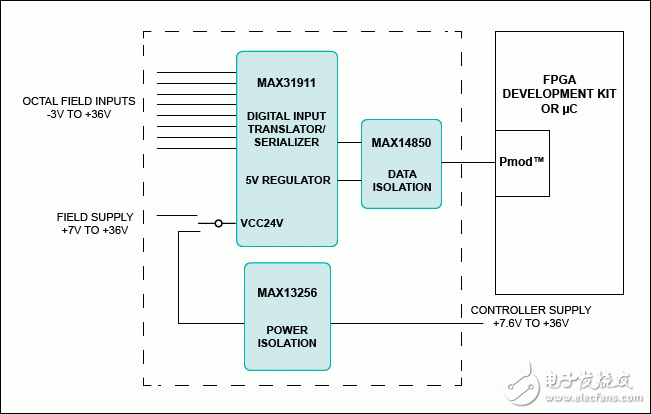
Binary/digital sensors and switches are often required in industrial control, industrial automation, motor control, and process automation applications. Systems often require many optocouplers to isolate the sensor channels. The Corona (MAXREFDES12#) subsystem reference design provides a front-end interface circuit for a programmable logic controller (PLC) digital input module that greatly reduces the number of isolated optocouplers. The reference design supports high voltage inputs (up to 36V), power and data isolation – all integrated in a small package. Corona is designed to integrate an eight-channel digital input level shifter/serializer (MAX31911), a data isolator (MAX14850), and an H-bridge transformer driver (MAX13256) for isolated power supply design. The Corona digital input circuit solution is primarily used for digital input modules in PLC, industrial automation, process automation and motor control applications.

Figure 1. Corona subsystem design block diagram
Features eight high-voltage input channels (up to 36V)
On-chip 8-1 serializer, SPI interface Internal 5V regulator Isolated power and data Small printed circuit board (PCB) area Device driver
C language source code example
Pmod? compatible specifications
Application building automation
PLC Digital Input Module Industrial Automation Motor Control Process Automation
Detailed hardware description
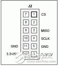
The Corona (MAXREFDES12#) Hardware Pmod specification allows for a variety of pin assignments for 3.3V and 5V modules. The module operates from a 3.3V or 5V supply and uses the SPI pin assignment as shown.

Table 1 shows the power requirements and Table 2 shows the currently supported platforms and ports.
Table 1. Power Requirements for the Corona Subsystem Reference Design
Power Type Jumper Shunt Power Name Input Voltage (V) Input Current (mA, typ)Isolated power JU1: 1–2 U3 VCAA 3.3 19.4
5 27.2
U1 VCC24V 12 13.6
24 14.5
Field power JU1: 2-3 U3 VCAA 3.3 19.4
5 27.2
U1 VCC24V 12 8.2
24 8.2
Table 2. Supported platforms and ports
Supported Platforms PortsNexys??3 platform (Spartan?-6) JA1
ZedBoard??platform (Zynq?-7020) JA1
The Corona subsystem is an isolated, eight-channel, digital input level shifter/serializer. The design includes an eight-channel digital input level shifter/serializer (MAX31911), an H-bridge transformer driver (MAX13256), and a six-channel digital isolator (MAX14850).
The MAX31911 (U1) is an industrial interface serializer that level shifts, conditions, and serializes the 24V sensor's and switch's digital outputs to produce a CMOS-compatible signal that the microcontroller can accept for industrial and process applications. Control and building automation applications. The device provides a front-end interface circuit for the PLC digital input module, which integrates current limiting, low-pass filtering and channel serialization processing circuitry. Compared to traditional discrete resistor divider schemes, input current limiting effectively reduces the power consumption of the field power bus. An optional on-chip low-pass filter flexibly debounces and filters the sensor output. The on-chip serializer greatly reduces the number of optocouplers used for isolation. In order to improve the anti-high frequency noise and fast electrical transient interference capability, the device can generate a multi-bit CRC, and every 8 bits of data is sent a check code through the SPI port. The on-chip 5V regulator can be used to power external optocouplers, digital isolators, or other external 5V circuits.
The MAX13256 (U2) provides an isolated, practical isolated power solution that supports 7.6V to 36V DC power supplies, utilizing a commercial TGMR-501V6LF Halo® transformer (primary to secondary side turns ratio of 1:1) and an external onboard full-bridge rectifier Convert it to an isolated 7V to 36V DC power supply.
The MAX14850 (U3) provides data isolation with a 3.3V or 5V voltage on the Pmod side (the Pmod power supply for the Nexys 3 and ZedBoard platforms is fixed at 3.3V). The voltage on the side of the MAX31911 is 5V. The resulting combined power and data isolation is 600VRMS.
To isolate the circuit on the utility board, move the shunt on jumper JU1 to the 1–2 position and apply 7.6V to 36V DC between terminals TP3 and TP4. If the on-board isolation circuit is not required, jumper JU1 The upper shunt is moved to the 2-3 position and a 7V to 36V DC voltage is applied between terminals TP1 and TP2. See Table 1 for information on jumper settings and input current requirements.
Push Wire Connectors,Custom Push Wire Connectors,Push In Connector,Quick Wire Connectors
Jiangmen Krealux Electrical Appliances Co.,Ltd. , https://www.krealux-online.com