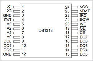
DS1318 pin configuration
 Counter Overview This application note demonstrates how to use the DS1318 elapsed time counter. The DS1318 has a 44-bit counter that provides a timing resolution of 244µs. The 44-bit counter is accessed through six 8-bit registers (Figure 1).
Figure 1. 44-bit counter configuration of DS1318
Conceptually, the 44-bit counter can be divided into a 12-bit sub-second counter and a 32-bit counter with a resolution of one second (Figure 2). If the application does not require sub-second resolution, you can access the 32-bit second counter.

Figure 2. 12-bit sub-second counter and 32-bit second counter.
In the example provided in this application note, the software subroutine continuously reads the value of the 32-bit second counter once per second, and outputs the time and date in ASCII format through the UART interface of the 8051 microcontroller (µC). The time and date are based on the time elapsed since January 1, 1970, 00:00:00, in seconds. The time corresponding to 00000000h is January 1, 1970, 00:00:00; the time corresponding to 42C924C0h is 2005/7/4 12:00:00.
Another subroutine configures the device as a periodic interrupt with a frequency of 1 Hz. Every time an interrupt occurs, the interrupt handler reads the counter data, converts the time into a date format, and outputs the data in ASCII format through URAT.
We also provide other routines in which you can perform the following operations on the DS1318: you can write user input data to the register; convert the time and date entered by the user to the time since January 1, 1970, The unit is second; write data to the counter. Another subroutine is used to read the DS1318 register and output the data in hexadecimal format.
How it works The hardware circuit in this application note puts the DS1318 data into the µC data storage space. µC accesses the DS1318 register by reading and writing data memory at the correct address.In this example, the DS80C323 low voltage, 8051 compatible microcontroller is used. Both user input data and program output data will be transferred to µC for communication through the RS-232 interface of the PC terminal emulator. Detailed information about the DS80C323 microcontroller in this application note can be downloaded from the company's website.
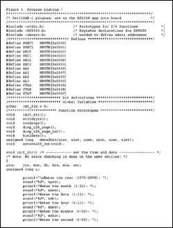
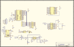
The program list is shown in Figure 3, and the circuit schematic is shown in Figure 4.

Download (TXT, 7K)
Figure 3. Program list

Detailed circuit diagram (PDF, 30K)
Figure 4. Circuit schematic
This POWER Bank possesses a lithium ion battery at its core, which takes
up to five hours to be completely charged. As for the output charging
speed, it stands at a thousand milliamp hours per hour.
The input
port is a micro USB, while the output port is in the form of a single
USB. There are two lights on display, for the purpose of indicating the
levels of charge. This power bank can be used up to or more than 500
full cycles. It is compatible with several commonly used gadgets such as
iPhone, iPod, mobile phones, and even digital cameras. Basically, it
fits well with any device that has a USB interface.
Portable Power Bank,Lithium Battery Power Bank,Lithium Battery Portable Charger,Lithium Battery Portable Power Bank
Custom Usb Gift company limited , https://www.customusbgift.com