When shape machining is performed on the cnc milling machine, since the milling cutter has a certain radius, the tool center (heart) trajectory and the workpiece shape do not coincide. If the tool radius is not considered, it is convenient to directly program the workpiece shape according to the workpiece shape. The size of the part is smaller than the pattern requirement (when machining the outer shape), or a large circle (when machining the inner shape), so make sure that the tool is offset by a tool radius along the normal of the workpiece shape. This is The so-called tool radius compensation command. When applying the tool radius compensation function, it is only necessary to program according to the workpiece shape trajectory, and then input the tool radius value into the cnc system. When performing the steps, the system will actively plan the tool center trajectory and hold the tool radius compensation to process the required requirements. The shape of the workpiece does not need to change the machining steps when the tool radius changes, which greatly simplifies the programming work. Practice has confirmed that ä¼¶ä¿ application of tool radius compensation, just configured tool radius compensation value, has a tense significance in cnc processing.
1 Change the tool compensation value to the appropriate tool change
In the active machining process of the part, the wear, re-grinding and even the change of the tool are usually generated. The change of the applied tool value can completely prohibit the labor of re-modifying the step when the tool is worn, reground or exchanged. In the process of part machining, the tool becomes smaller due to wear and tear. If the workpiece deviation exceeds the workpiece tolerance, the machining requirements are not met. Assume that the original tool offset is r, and after a period of processing, the tool radius is reduced.  At this time, you can only modify the tool compensation value of the tool: from the original r to
The processing requirements can be met without changing the original steps. Also, this can be done as the tool is reground. When it is necessary to change the tool, the radius value of the new tool can be used as the tool compensation value instead of the tool compensation value in the original step. It can be seen that it is precisely because the change of the tool compensation value is suitable for the change of the tool, and the processing requirements can be satisfied without changing the original steps. Therefore, the programmer can also preliminarily affirm the tool size to hold the programming in an environment where the actual tool size is unknown. In actual machining, the radius compensation can be replaced by the actual tool radius instead of the assumed tool radius.
2 Change the tool compensation value to achieve the rough and finishing of the part
Tool radius compensation has another very tight use. If the tool center and workpiece shape offset values ​​are artificially not a tool radius, but a given value, it can be used to process the coarse and fine machining titles. In the roughing process, the actual radius of the tool plus the finishing allowance can be entered as the tool radius compensation value, and only the actual radius value of the tool is input during finishing, such as allowing the roughing and finishing to take one step. The compensation method is: set the finishing allowance to  , the tool radius is r, as shown in Figure 1: Finally, the manual input tool offset value is
  Then, the roughing can be completed to the position of the dotted line; in the finishing process, the radius value r of the tool is input to complete the final shape finishing.
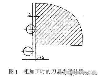
figure 1
3 Change the tool compensation value to correct the machining of the part
The combination of tool radius compensation and sub-steps not only simplifies programming, but also allows for roughing, finishing, and machining corrections to ensure the processing of the character. The following is clarified with a processing step, and the part drawing is shown in Figure 2.
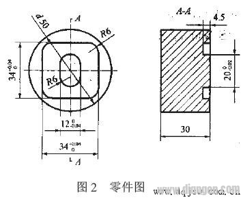
figure 2
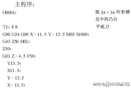
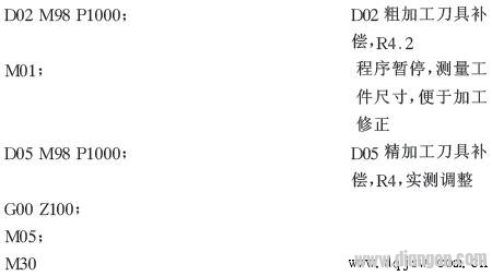
Substep
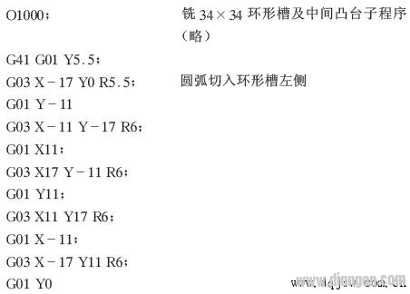
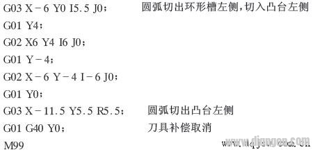
In the main step, use M01 to stop the step. At this time, measure the workpiece size, figure out the difference between the workpiece and the part size, and input the difference compensation into D05. In the finishing tool compensation, the workpiece can be processed. Ask to ensure the quality of the processing.
4 Use tool radius compensation to keep an eye on things
The front describes the application of tool radius compensation and the just-configured tool radius compensation value in the cnc machining. However, in actual use, be sure to pay attention to the following events:
a) The cutting surface should be prohibited when using the tool radius compensation: When using the tool radius compensation and the tool radius compensation, the tool must move in the compensated plane, and the moving partition should be greater than the tool radius compensation value. If the machining radius is smaller than the inner arc of the tool radius, the radius compensation will result in overcutting, only the transition fillet  In the environment of tool radius r + finishing allowance, the cutting is usually carried out; if the bottom width of the milling groove is smaller than the tool diameter, the cutting will also occur at this time;
b) G41, G42, G40 must be used in G00 or G01 mode. G41, G42 can not be reused, and do not agree to have two consecutive non-moving instructions when using;
c) D00 - D99 is the tool compensation number, and D00 means the tool compensation is canceled. The tool offset value must be set in the compensation memory before machining or running.
In short, the tool compensation value has a very tight effect in the cnc processing. The correct and precise step of using the knife compensation value and the knife compensation principle is the tension factor for the validity and accuracy of the cnc processing.
Prime View International Co., Ltd. 's products include ultra-thin and light, narrow bezels, transparent displays, LTPS, OLED, and touch solutions. PVI also has the most complete generation production line from 3.5G, 4G, 4.5G, 5G, 6G, 7.5G to 8.5G, which can provide a variety of LCD applications required panel products, size range from 1.2 "to 71" TFT-LCD Panel.
We continuously improve manufacturing technology on the research and development, including simplifying process, highly automated, and reducing components, etc., in order to improve the production efficiency, increase production capacity, more can improve the quality of products. Including strict sampling detection scheme, the condition of simulating various climate environment and the external force to test the product, and for different electronic application products to accurate detection. In addition, the company is constantly improving the process to improve efficiency and productivity, reduce production costs, in order to provide customers with more real-time, more competitive products and services, so as to achieve a win-win situation with customers to create profits.
Other Brand TFT-LCD,Lg Tft,Tft Color Screen,Tft Raspberry Pi 3,Arduino Mega Tft Shield
Tonya Display Limited , https://www.tydisplay.com