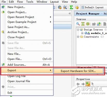
Since Xilinx has done most of the work for us, it is very simple to streaking the peripherals. If you don't use Linux and graphical interface display, probably my work will be completed early. The last time we have successfully generated the BitStream file, continue the last operation, open the PlanAhead project, select Export Hardware for SDK, as shown below:
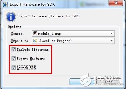
In the pop-up window, select the Launch SDK, and then enter the SDK interface after OK.
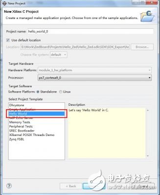
The method of writing streaking software under the SDK interface has been fully introduced in the ZedBoard_CTT document. The only difference between this and the official documentation is the need to add the underlying code that controls the AXI bus device. First create a new C project.

Select Hello World for the project template and click Next.
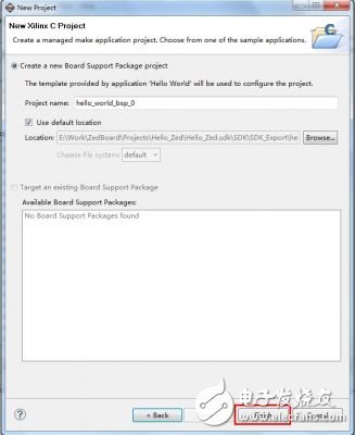
The BPS part can be used by default, and Finish is completed.
Then add the control code for our own my_gpio peripheral. Will not control AXI bus devices? It doesn't matter, since the configuration item that generated the driver was selected when creating the peripheral, Xilinx has automatically generated the streaking control code. The code is located in the file directory of the XPS project. The path of the rabbit here is "\Hello_Zed\Hello_Zed.srcs\sources_1\edk\module_1\drivers\my_gpio_v1_00_a\src\", and drag the my_gpio.h directly into the hello_world project on the left side of the SDK. And add a reference to my_gpio.h in the helloworld.c file: #include "my_gpio.h" Some children's shoes may encounter problems when compiling, suggesting that the xbasic_types.h file could not be found. At the same time, a small cross is displayed in the lower left corner of the my_gpio.h file.
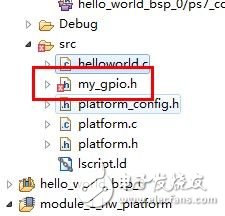
When this problem occurs, you can manually add the path to this header file, usually in the Xilinx ISE installation directory, on my computer: #include"D:\Xilinx\14.2\ISE_DS\EDK\sw\XilinxProcessorIPLib\drivers\ Common_v1_00_a\src\xbasic_types.h" If there is no problem compiling the project at this time, you can start writing the test code. Some functions that control AXI bus device registers, such as mReadSlaveReg and mWriteSlaveReg, are defined in my_gpio.h. Through these functions, the contents of the registers can be read and written. It should be noted that in order to control the peripherals, you need to know the physical address of the device. The address can be viewed in the XML file in the project. For example, the address of the my_gpio device is 0x75C00000.
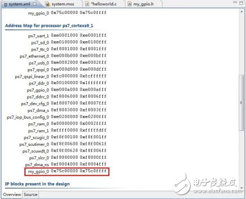
Here is a simple test case to test if our peripherals meet the design requirements. Its function is: read two register values, modify the register according to the terminal input, and finally read out the verification modification effect again. The code is as follows:
#include #include "platform.h"
#include "my_gpio.h"
#define MY_GPIO_ADDR 0x75C00000 //Device physical address
int reg0, reg1;
int main (){ init_platform(); //Read register initial value
printf ("======= My_GPIO Test =======");
printf ("Reading my_gpio registers..."); reg0 = MY_GPIO_mReadSlaveReg0(MY_GPIO_ADDR, 0); reg1 = MY_GPIO_mReadSlaveReg1(MY_GPIO_ADDR, 0)
Printf ("Reg0=0x%x, Reg1=0x%x", reg0, reg1); //Write data to the register
printf ("Input Reg0.");
scanf ("%d", ®0);
printf ("Input Reg1.");
scanf ("%d", ®1);
printf ("WriTIng to my_gpio registers..."); MY_GPIO_mWriteSlaveReg0(MY_GPIO_ADDR, 0, reg0); MY_GPIO_mWriteSlaveReg1(MY_GPIO_ADDR, 0, reg1); //Read register to verify the result
printf ("Read my_gpio registers..."); reg0 = MY_GPIO_mReadSlaveReg0(MY_GPIO_ADDR, 0); reg1 = MY_GPIO_mReadSlaveReg1(MY_GPIO_ADDR, 0);
printf ("Reg0=0x%x, Reg1=0x % x ", reg0, reg1) ; cleanup_platform (); return 0;} let us write code Zynq, run it and see it First compile the project, select Program FPGA after completion, and load the logic configuration for the PL part.
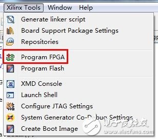
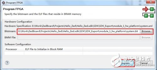
Because the BitStream file has been selected when exporting from PlanAhead to the SDK, this column has been automatically completed. If the path is not automatically added, it can be manually added according to the address in the figure. Click Program to start downloading configuration data.
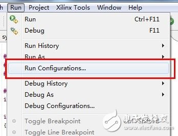
Wait a moment, after the Program is complete, select Run ConfiguraTIons to configure the run options.
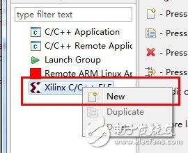
In the pop-up window, right-click on Xilinx C/C++ Elf and select New to create a new Debug item.
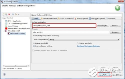
Select the new hello_world_0 Debug item and click Run to run the code. Here the C / C + + ApplicaTIon column has been automatically filled in the path of the elf file, if not filled (maybe the project has not been compiled), manually added from the Debug folder. The options in Run ConfiguraTIons are all configured by default. For the functions and setting methods of these options, please refer to the ZedBoard_CTT documentation, which will not be described here.
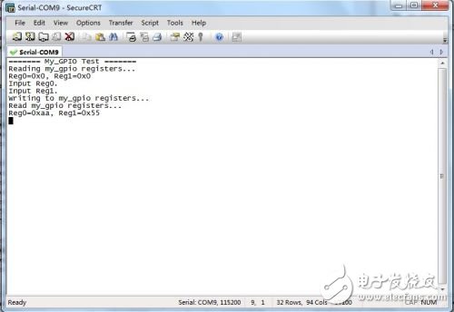
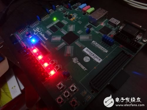
After the code runs, open the serial terminal software (SecureCRT for rabbits). At 115200bps baud rate, the serial port starts to output information. The default values ​​in both registers (both 0x0) are displayed first, then SW7, SW5, SW3, and SW1 are dialed up to a high level, and the others remain low. Then enter 85 and enter via the keyboard twice, that is, write 0x55 to both registers. Since register 0 is a read-only register, its contents change only according to the state of the Switch. Therefore, the result of reg0 is 0xAA, which is the value we set for the switch, and LED0, LED2, LED4, and LED6 will be lit. The code works normally, the serial port output is as follows:
Measured photos:
It's really simple, Xilinx seems to be doing a good job at the user. After verifying the correctness of the logic, it is time to start preparing for Linux control peripherals, see next time. Source: Electronic lazy rabbit blog
Busway Temperature Monitoring System
The busway temperature monitoring system is composed of monitoring host and temperature and humidity acquisition module, which is used for the temperature monitoring of low-voltage dense busway. The main monitoring temperatures include: the temperature at the busway connection (the temperature of each phase contact point), the busway housing temperature, and the ambient temperature, and can display, upload, store and fault alarm the data in the monitoring unit.
Busway Temperature Monitoring System,Thermostatic Temperature Control Valve,Temperature Control Box Mod,Bus Bar Temperature Monitoring
Jiangsu Sfere Electric Co., Ltd , https://www.elecnova-global.com


