When the output voltage is lower than the specified value, it reflects an abnormality in the input DC power supply, the switching regulator, or the output load. When the input DC power supply voltage drops below the specified value, the output voltage of the switching regulator drops and the input current increases, which jeopardizes the switching transistor and jeopardizes the input power. Therefore, undervoltage protection should be set. Simple undervoltage protection is shown in Figure 1.
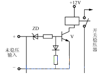
Figure 1 Input undervoltage protection
When the voltage value of the unregulated input is normal, the Zener diode ZD breaks down, the transistor V turns on, the relay acts, the contacts pull in, and the switching regulator is powered. When the input is lower than the minimum allowable voltage, the Zener diode ZD is not connected, V is cut off, the contact is tripped, and the switching regulator cannot work.
Inside the switching regulator, the output voltage drops due to a malfunction of the control circuit or a failure of the switching transistor; a short circuit in the load also causes the output voltage to drop. Especially in the step-up or inverting step-up DC switching regulators, undervoltage protection is closely related to overcurrent protection and is therefore more important. The implementation method is to connect the voltage comparator to the output of the switching regulator, as shown in Figure 2.
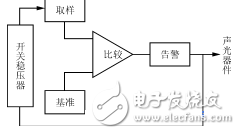
Figure 2 Undervoltage protection block diagram
Normally, the comparator has no output. Once the voltage drops below the allowable value, the comparator flips and drives the alarm circuit. At the same time, it is fed back to the control circuit of the switching regulator to turn off the switching transistor or cut off the input power.
36v undervoltage protection circuit diagram (2) circuit working principle:The circuit consists of 11 components, the circuit is simple and responsive, and its application range is also wide. The voltage range and power capacity can be changed by using different devices, and the chip components can be used to further reduce the volume.
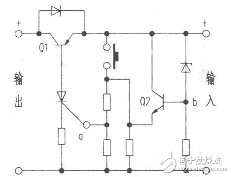
The circuit is shown above. In the case of normal voltage, the potential at point b is higher, so the potential at point a is correspondingly higher; the thyristor is turned on, so Ql is turned on, and the load at the output terminal is normal. When the input voltage drops to a certain level. The potential at point b decreases correspondingly, and the degree of conduction of Q2 decreases, so that the potential at point a decreases, and the thyristor is turned off, so that Ql is turned off, and the power supply to the load is cut off. When the external voltage is normal or the battery is fully charged, it can be manually reset. If you need to install the indicator circuit, you can install it as shown below, and use the three-color LED to indicate.

The circuit can be used for over-discharging protection of lead-acid batteries, such as electric vehicles, charging lamps, miner's lamps, etc., and can also be connected to a low-voltage DC power supply circuit to protect the load. Here, in the case of applying a lead-acid battery, an undervoltage protector should be added as much as possible, and protection can be implemented when the cell voltage drops to about 1.9V to extend the life of the battery.
Note that this circuit should select the device reasonably in different applications, and leave a certain margin to ensure the stable operation of the circuit.
36v undervoltage protection circuit diagram (3) circuit working principle:When the power supply generates overcurrent, overvoltage, and undervoltage faults, V1, V2, and V3 are high. The D flip-flop detects the pulse level and latches the fault. It is then sent to the OR gate so that the fault output V7 is high. V7 is divided into two ways: one is sent to the drive circuit, the drive is turned off, the main circuit IGBT switch is protected; the other is sent to the control protection circuit, and the input of the three-phase 380 is turned off.
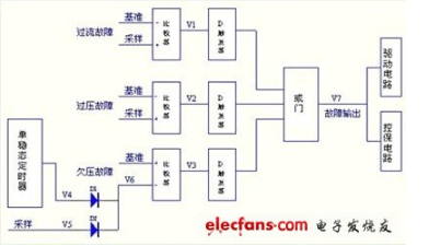
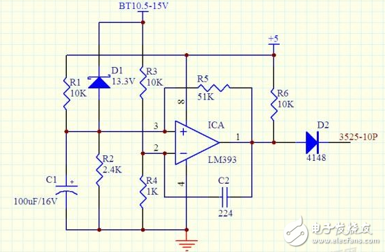
When doing the inverter, we always design an undervoltage and overvoltage protection circuit. The circuit in the figure has the following characteristics:
1. Only one unit of comparator is used to complete the undervoltage and overvoltage protection functions, so it is relatively simple compared to the circuit with two comparators.
2. When the BT voltage drops below 10.5, the comparator outputs a high level, turning off the PWM output of the 3525. Because the comparator adds a positive feedback resistor R5, the circuit has a hysteresis value. At this time, if the BT rises to At 12.2V, the comparator is inverted, the output is low, and the inverter is automatically restarted.
3. When the BT voltage rises above 14.8 for some reason, D1 turns on, the comparator outputs a high level, and the inverter is turned off. When the D1 voltage regulation value is 13.3V, the protection threshold is 14.8V. If there is no suitable voltage regulator tube, it can be used in series with 10V+3.3V. The effect is the same.
The above is the parameter at 12V. If you want to use it for 24V system, just change the parameters of several resistors.
The schematic of the input overvoltage and undervoltage protection circuit is as follows:
1, schematic: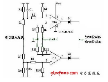
The input and undervoltage protection principles of the AC input and DC input switching power supplies are approximately the same. The sampling voltage of the protection circuit is derived from the input filtered voltage. The sampling voltage is divided into two ways. One is divided into R1, R2, R3 and R4 and then input to the comparator 3 pin. If the sampling voltage is higher than the reference voltage of the 2 pin, the comparator 1 pin outputs a high level to control the main controller. Shutdown, no output from the power supply. The other way is divided into R6, R8, R9, R10 and then input to the comparator 6 pin. If the sampling voltage is lower than the 5 pin reference voltage, the comparator 7 pin outputs a high level to control the main controller to turn off, and the power supply has no output. .
36v undervoltage protection circuit diagram (6) circuit working principle:The figure shows. The mains 220V AC power supply is smoothed by capacitor C1C1, silicon diode, VD1 half-wave rectification, capacitor C2 filtering and voltage regulator VD2. Provide 10~12V working voltage to the delay and undervoltage protection device circuit.
When the grid voltage is momentarily powered off and the power supply is immediately restored, the single-junction transistor VT is turned off due to the extremely low potential, and the relay K is powered off, and the refrigerator stops working. At this time, the power supply is charged to the capacitor C3 via the normally closed contact K1-1 of the relay K and the resistor RP. When the voltage on the C3 rises to a constant value, VT is turned on, and the relay K is electrically operated. This is because the normally open contact is connected with the normally closed contact K1-1, the circuit power supply of the protection device is still in the on state; the normally open contact K2-1 is closed, and the refrigerator is powered on, thereby realizing an instant Power failure and power supply delay protection. The LED is lit, indicating that the protection function is working.
If the grid voltage drops below 185V. After the voltage of the step-down and rectification is far below 10V, the voltage across C3 is not enough to make the single-junction transistor VT turn on, and the relay K is discharged and loses power. The power of the refrigerator is cut off to ensure that the refrigerator is not at a low voltage. Run under load conditions.
Component selection:VT is a single junction transistor, BT33-BT35 is used. The RP is a trimmer resistor and a small potentiometer can also be used. VD1 is an IN4007 silicon rectifier diode. VD2 is a Zener diode, preferably 2CW110. The LED is a red high brightness LED. C1 is a CBB capacitor with a withstand voltage of 400V. C2, C3: Electrolytic capacitor with a withstand voltage of 35V and minimum leakage current. K10-12V DC relay, two sets of contacts, JQX- is 13F2Z type.
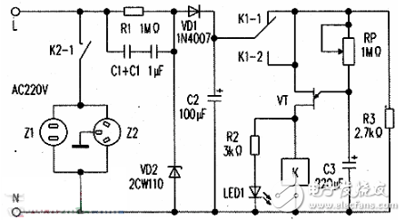
Remember: When assembling, a set of two contacts K1 of the relay should be connected together. To ensure that the relay is closed, the set of contacts is always closed. Delay time, should adjust the resistance of RP or the capacity of C3, the general delay time is preferably 5 to 8 minutes.
During the debugging process, ensure that the AC voltage is lower than 185V to achieve undervoltage protection. The most critical is to adjust the voltage across C3. I used a 300W regulator to reduce the 220V voltage to 185V and connect it to the undervoltage protection device. Then adjust the RP so that the relay contacts just pull in and work stably, and then reduce the input AC voltage below 185V, the relay is released, which means the adjustment is completed. Note: The relay test adjustment should be balanced with the delay adjustment. It should be adjusted patiently and carefully. Others have no special requirements. As long as the welding is correct, it can be installed.
Piezoelectric Elements For Inkjet Piezo Transducer
Piezoelectric ceramic ring
Applications: ultrasonic vibration tranducer for inkjet printer
Vibration mechanism of inkjet printer:
Generally, it is composed of piezoelectric ceramics and driving rods. By high-frequency electric excitation, piezo ceramics produce high-frequency ultrasonic vibration (above 60 kHz or higher), which is transmitted to the driving rod and generates high-frequency micro-displacement (back and forth expansion) at its front end.
Piezo ceramics components features :
1. High vibration amplitude and can withstand higher power.
2. The product has high reliability, strong maintainability, and is not easy to break down or off-line.
3. The frequency can be adjusted in a wide range, generally within the range of 10KHz.
Yuhai support all the new developping transducer, Welcome the customized elements inquiry.
The present piezoelectric elements for Inkjet piezo transducer is following :
Piezo rings OD4*ID2*2.5mm price USD1.20/pc, 2000pcs
Material: PBaS-4
Fr.: 694 KHz ±5KHz
K33: ≥0.55
Tg loss <0.5%
Ct 60pF ±12.5%
Piezo rings OD4*ID2*2.5mm price USD1.20/pc, 2000pcs
Material: PSnN-5
Fr.: 626KHz ±5KHz
K33: ≥0.57
Tg loss < 2%
Ct 53pF ±12.5%
Piezo rings OD6*ID2.5*2mm price USD1.50/pc, 2000pcs
Material: PZT-41
Fr.: 785 KHz ±5KHz
K33: >0.53
Tg loss < 0.5%
Ct 107 pF ±12.5%
Piezo rod OD3*7mm price USD1.20/pc, 2000pcs
Material: PLiS-51
Fr.: 192 KHz ± 3KHz
K33: >0.62
Tg loss < 2%
Ct 18.7 pF ±12.5%
Inkjet Piezo Transducer,Piezoelectric Vibration Transducer,Piezoelectric Rings,Piezoelectric Elements For Inkjet Piezo Transducer
Zibo Yuhai Electronic Ceramic Co., Ltd. , https://www.yhpiezo.com