Definition of signal integrity: Signal Integrity (SI) refers to the quality of the signal on the signal line. Poor signal integrity is not caused by a single factor, but by a combination of factors in the board design. When the signal in the circuit can reach the receiving end with the required timing, duration and voltage amplitude, the circuit has good signal integrity. Signal integrity issues arise when the signal does not respond properly.
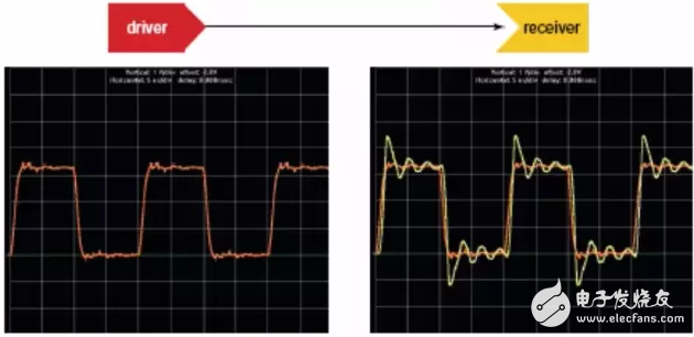
Signal integrity includes:
1, Waveform integrity (Waveform integrity)
2, timing integrity (TIming integrity)
3, power integrity (Power integrity)
The goal of signal integrity analysis is to achieve the required waveform integrity, timing integrity, and power integrity requirements with minimal cost and time.
We know that power supply instability, power supply interference, crosstalk between signals, and reflection during signal transmission can all distort the signal. Looking at the picture below, you will know the ideal signal after: reflection, crosstalk, Jitter, what is the last ghost.
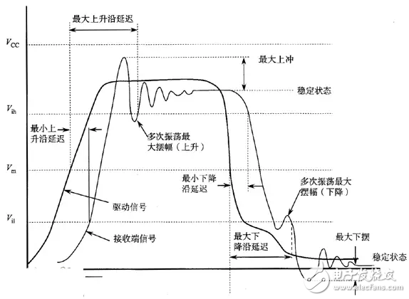
If your oscilloscope tests such a signal, you will definitely ask why this is the case and how to solve it.
First let's talk about reflection:
Reflection - initial wave
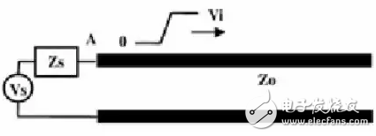
When the driver transmits a signal into the transmission line, the magnitude of the signal depends on the voltage, the internal resistance of the buffer, and the impedance of the transmission line. The initial voltage seen at the driver side is determined by the internal resistance and the partial impedance of the line impedance.
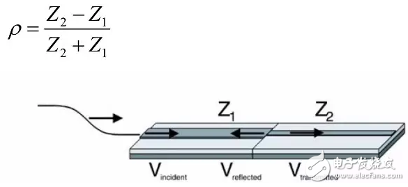
Reflection coefficient
? -1≤Ï≤1
No reflection occurs when Ï=0
Fully specular reflection occurs when Ï = 1 (Z 2 = ∞, open circuit)
Full negative reflection occurs when Ï = -1 (Z 2 =0, short circuit)
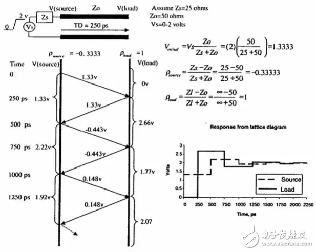
The initial voltage is the source voltage Vs (2V) divided by Zs (25 ohms) and transmission line impedance (50 ohms).
ViniTIal=1.33V
Subsequent reflectance is calculated according to the reflection coefficient formula
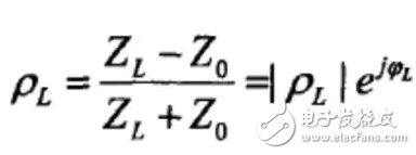
The reflectance at the source is calculated as -0.33 according to the reflection coefficient formula according to the source impedance (25 ohms) and the transmission line impedance (50 ohms);
The reflectivity of the terminal is calculated as 1 according to the reflection coefficient formula according to the terminal impedance (infinity) and the transmission line impedance (50 ohms);
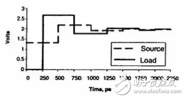
We obtained this waveform by superimposing the initial pulse waveform according to the amplitude and delay of each reflection, which is why the impedance mismatch caused the signal integrity to be poor.
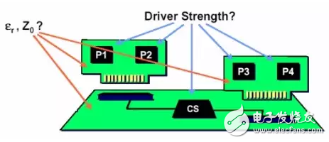
The impedance has to be changed due to the presence of connections, device pins, trace width variations, traces, and vias. So reflection is inevitable.
Voltage, the latter current changes, naturally radiate electromagnetic waves
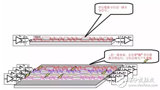
Crosstalk is the undesired occurrence of adjacent transmission lines due to electromagnetic coupling when the signal propagates on the transmission line.
Voltage noise.
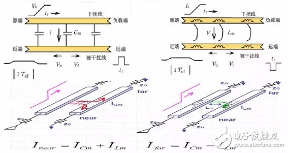
Crosstalk is caused by electromagnetic coupling, and coupling is divided into capacitive coupling and inductive coupling.
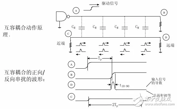
Capacitive coupling is due to voltage changes on the aggressor (Aggressor) on the victim (VicTIm)
Electromagnetic interference caused by induced current;
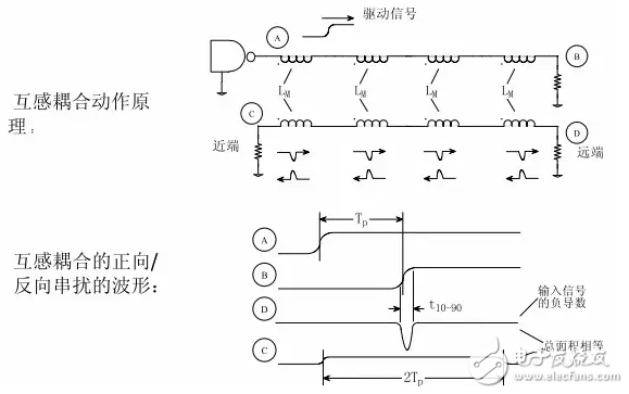
Inductive coupling is the electromagnetic interference caused by the magnetic field generated by the current change on the interference source causing the induced voltage on the interfered object. Thus, a signal passing through a conductor causes two different types of noise signals on adjacent conductors: a capacitively coupled signal and an inductively coupled signal.
Inductive coupling:
Capacitive coupling:
Cbd Vape Products Oem,D8 Vape Pen Oem,Cbd Disposable Vape Pen Oem,China Cbd Vape Products Oem
Shenzhen MASON VAP Technology Co., Ltd. , https://www.cbdvapefactory.com