Yesterday we sent an article related to a paper published in Nature, which is very valuable. The paper stated that they solved the minimum fleet problem by proposing a mathematical model. This article is an interpretation of Professor Zhang Jiang's thesis: With the popularity of shared travel and the possibility of autonomous driving of the entire road network, we can realize an utopian urban traffic system managed by algorithms. Such a system can achieve On-demand urban mobility, that is, dynamically allocate the delivery vehicles according to each person's needs, so as to achieve overall optimization. Technically speaking, the author first mapped the on-demand traffic problem into an idealized mathematics problem, the smallest fleet problem, and given this problem in combination with the actual 1.5 billion travel data of New York City taxis. Optimal solution. The results show that using an algorithm-managed traffic system can reduce the number of taxis by about 40%. Even when considering that travel needs may be submitted in real time, this reduction can reach 30%. Therefore, the solution of this problem can not only greatly improve the operating efficiency of the shared travel system, but also provides a very good demonstration case for the future social model of artificial intelligence governance.

The three major trends of automatic driving and networking and shared travel modes will revolutionize our future transportation systems and modes of travel. This makes the entire transportation system possible to be uniformly managed by algorithms. Therefore, a utopian transportation system will no longer be far away. In it, the algorithm can dispatch each vehicle so that the overall operating efficiency of the system can be maximized, and environmental protection can be maximized. This model will greatly outperform the existing modes of transportation. Private cars, taxis and buses will likely become history.
To achieve such a utopian transportation system, the algorithm is one of the most important components. Because, in order to meet the travel needs of all citizens, we need to rationally dispatch every self-driving car that runs on the road network so as to: (1) be able to meet the travel needs of every citizen as efficiently as possible; ( 2) It is possible to achieve the minimum cost as a whole, that is, to achieve as much travel needs as possible with the minimum number of vehicles and traffic. Does this algorithm exist? A collaborative research team from MIT, the Italian Institute for Pizza Information and Communication Technology and Cornell University and Cornell Technology gave a positive answer.
1. The smallest fleet problem
The team first reduced people's travel needs to a simple math problem. Let us consider the travel needs of six people A, B, C, D, E, and F, as shown in Figure 1:
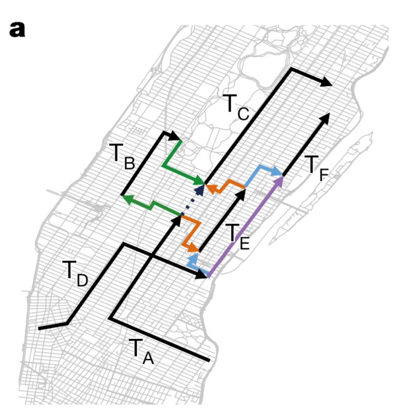
Figure 1: Schematic diagram of six people's travel tracks ABCDEF, respectively T_A, T_B ... T_F
Each leg of T_A, T_B, ..., T_F represents the travel requirement of a user, that is, the user wants to start from the time point t_p, and the point l_p, and reach the point l_d at the time t_d. Among them, t_p is the earliest time that the self-driving car can receive user A, and t_d time point can be estimated according to departure time t_p and road network conditions (traffic flow and other factors).
Assume that we can schedule a group of self-driving teams to meet the travel needs of this group of users. Thus, we can assign different cars to each travel route, and let the same car meet the travel needs of two users in succession. Only the second user's travel needs are separated from the last user's completion time and space. Too far to complete. In other words, a self-driving car can continue to pick up another user after completing a user's task, as long as the user's required time t_p and the self-driving car complete the last task's end time t_d, and Considering that the interval between the last l_d and the next l_p of the self-driving car is not too large, it is sufficient.
In Fig. 1, the colored broken line segment is the conversion path of a self-driving car after completing the previous task and further completing the next task. For example, when a self-driving car receives A and completes a mission, it may follow the green arrow to the starting point of B to pick up B and send it to B's destination, and then follow the green line arrow to C's starting point. To meet C's needs.
Of course, the self-driving car that picks up A can also walk along the orange arrow to the starting point of E after A finishes, and then pick up the C again.... Therefore, our fleet of self-driving cars can have different ways to meet as many travel needs as possible given the location, time, and destination of a given group of users.
Then, the so-called minimum fleet problem is: Given a given set of travel requirements, can we serve all travel tasks with the minimum number of self-driving cars?
It can be thought that if we can solve this problem mathematically, then we can operate our self-driving transport system in a most "economical" way, so as to save energy and protect the environment.
2. Vehicle sharing network
However, such an abstract problem is difficult to solve all of a sudden. We need an intermediate transition tool. This is the "Vehicle-shareability network". This network model is a network model for describing shared traffic patterns proposed in reference [7]. He can be used to model different vehicle allocation scenarios. For example, the directed network of FIG. 2 is a vehicle sharing network that models the different vehicle allocation schemes corresponding to FIG. 1:
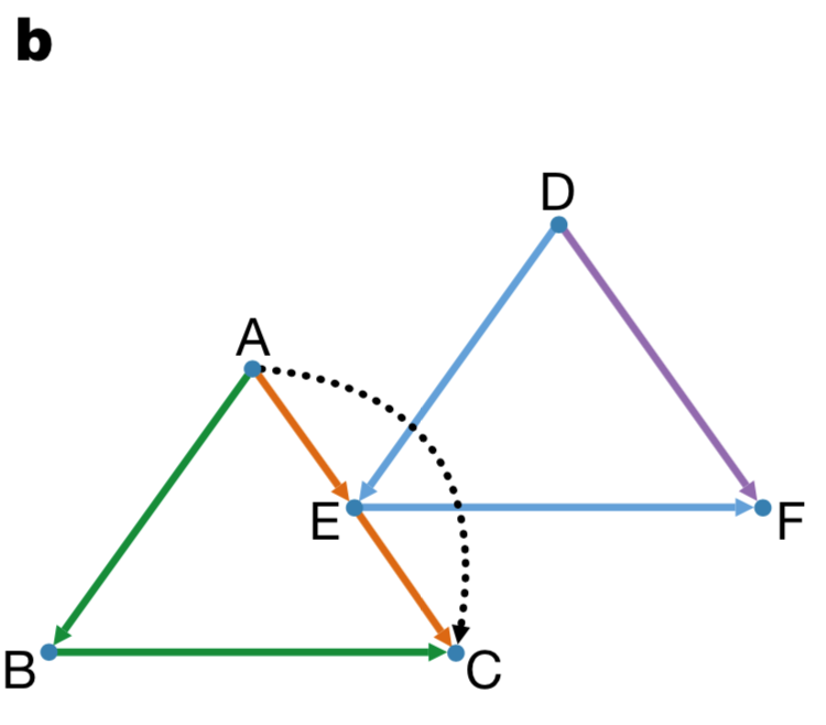
Figure 2 The vehicle sharing network corresponding to Figure 1
In this network in Figure 2, a node corresponds to the travel requirement of a user in Figure 1, so A corresponds to the T_A travel path in Figure 1. A directed edge connection in the figure corresponds to a possible task switch. In other words, if there is a border between nodes A and B, it means that the self-driving car may complete the task A after completion. B. If there is no link, it means that the self-driving car may not finish task B again after the completion of the A task due to the long time interval or the long distance.
The possible path switches in FIG. 1 all correspond to the directed edges in FIG. 2 . Among them, the completion task plan of a certain car corresponds to a directed path of the same color in FIG. 2 . For example, the green path in FIG. 2 corresponds to the self-driving cars that successively transfer three users A, B, and C.
To meet the travel needs of all people, it is to find a set of path division schemes, so that these paths can cover all points on the shared travel network (service all travel requirements). Obviously, there are many such path division schemes. What is the best?
It is very interesting that this problem of the minimum coverage path is precisely the minimum fleet problem described above. Thus, using the vehicle sharing network, we skillfully transformed the minimum fleet problem into the problem of the minimum path coverage on the shared network.
In summary, we can use the vehicle sharing network to construct a "least-path coverage problem" starting from the actual data. Its steps are as follows:

Figure 3 The minimum fleet problem solving process
Next, how can this problem be solved? The bad news is that this is an NP-hard problem for the general sense of the optimal path coverage problem. We cannot find an effective solution to the problem; but the good news is that due to the special nature of our vehicle sharing network, That is, it is a directed acyclic graph. This means that we can use the Hopcroft-Karp algorithm to find an effective solution to this problem (see the paper appendix for details).
3. Operational effects of Utopia Traffic
Next, let us take a look at how this optimal sharing scheme works. The authors combined data from all New York City taxis in 2011 to build a vehicle sharing network. This dataset contains 1.5 billion travel records. Each travel record corresponds to the time the user was picked up by a taxi. That is, t_p, location, ie, l_p, and at what time, t_d, the user was sent The designated location, which is l_d. In this way, we can use the algorithm flow shown in Figure 3 to calculate the optimal number of taxis for each day, or even hour, and compare them with the actual number of taxis used.
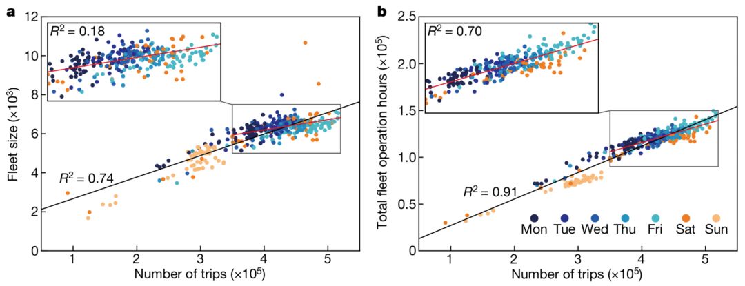
Figure 4 Calculated on taxi travel data in New York City
The relationship between the optimal number of vehicles or the total fleet operating time and the number of different sunrise trips
First, as shown in Figure 4, we have seen that the optimal number of taxis will increase linearly with the increase in people's travel needs. Different colored dots indicate different working days (Monday, Tuesday, etc.). The graph on the right shows that the total fleet time has increased linearly with the number of trips. We have seen that when the number of trips is between 300,000 and 550,000, the slope of growth will be smaller, which indicates that not only the travel density, but also the mode of people's travel will affect the optimal number.
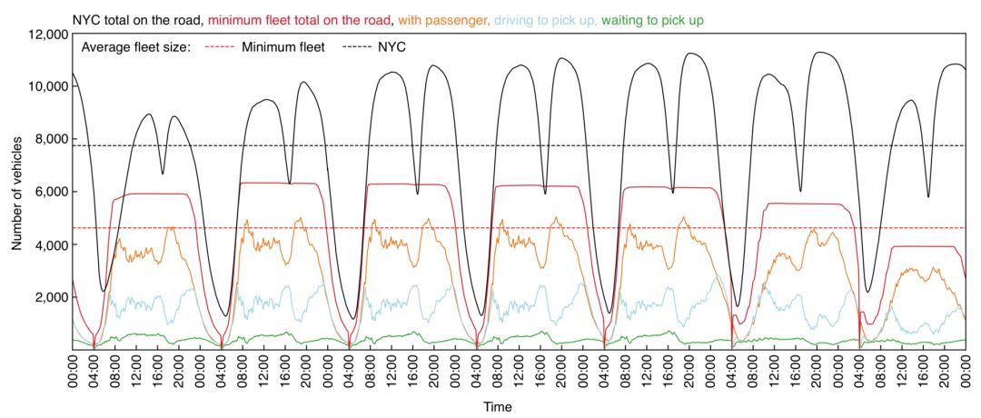
Figure 5 Curve of the optimal fleet number and actual taxi usage over time
Second, Figure 5 shows the actual number of taxis (black), the number of optimal taxis (red), and the number of taxis (other colors) in different modes as a function of time. The dotted line corresponds to their average value. We have seen that if we use algorithms to manage the entire transportation system, we only need an average of 60% of the actual number of taxis per day, which reduces the use of 3,000 taxis!
4. More realistic considerations
Although the figure of 60% is quite astonishing, this figure is based on the assumption that all the demands in one day are submitted to the optimization system at the same time, so that the system can systematically arrange the travel of all vehicles, thereby optimizing the travel configuration. .
However, the reality will be much more “skinny†than this situation: the demand for travel within a day cannot be submitted to our server at the same time, but must be submitted to the system one by one in real time. In this case, we need to improve the algorithm. Thus, the author provides two kinds of improvements, namely on-the-fly algorithm and batch algorithm.
In the first algorithm, travel requirements are processed one by one in sequence. The system will automatically select a vehicle that allows the user to wait for the shortest time in all vehicles.
In the batch algorithm, the system collects a batch of demand data every interval δ = 1 minute, and uses the maximum matching algorithm to satisfy all users, and allows the shortest waiting time.
To compare these two algorithms, we use a slightly larger number of vehicles than the smallest fleet problem (N_{min}x, where N_{min} is the minimum number of vehicles and x is a slightly larger parameter than 1) to operate and compare The percentage of total service demand of two different algorithms is used as an indicator of the evaluation. The results are shown in the figure below:
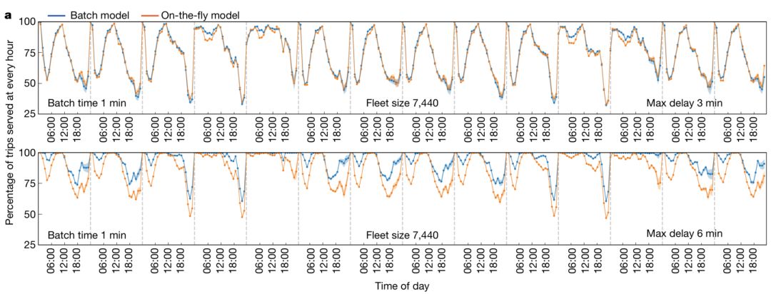
Figure 6: Change in service ratio over time for direct and batch algorithms for different hours of day
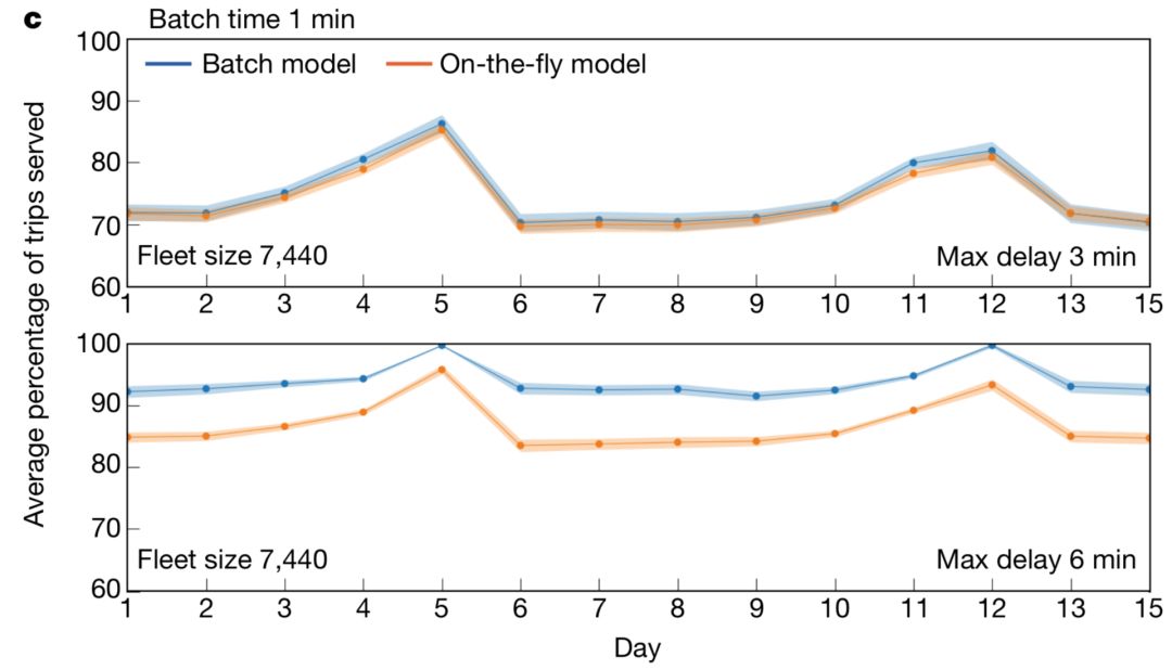
Figure 7: Percentages of the percentage of services that can be served by different date direct and batch algorithms
The abscissa in Figures 6 and 7 is time, and the ordinate is the percentage of travel for the algorithm service. The higher the percentage, the better the algorithm. We see that the percentage of service for the batch model is higher whether it is measured in hours or in days.
By combining actual travel data and optimization algorithms, we have found that using the batch model, we can use 70% of the actual number of taxis to serve more than 90% of travel needs. Although this is not a cool model, it also shows that considering the real-time services, we can still achieve as high efficiency as possible and enough user satisfaction.
5. The future of artificial intelligence society
Finally, the author concludes that although this algorithm only solves single-row mode and single-vehicle optimization problems, it can be fully extended to multiple modes of mixed-transit traffic optimization, which provides us with more solutions to travel problems. Imagination space. Although more convenient travel may well stimulate people's need for more travel, overall, an autonomous driving system managed by efficient algorithms will inevitably make our traffic more efficient and intelligent.
The author even believes that the significance of this work may also extend to more shared economic models. Using algorithms instead of human subjective decisions to unify and manage the entire macro system will become possible in the future.
Key Specifications/Special Features:
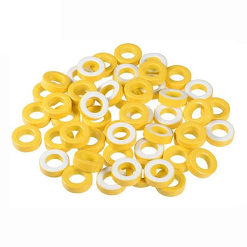
- Different dimensions of toroidal cores made of iron powder,sendust, MPP, high flux
-
Iron powder toroidal cores used in:
- Output chokes for switching power supplies
- Constructed EMI nose filters
- Pulse transformers, DC output, input filters
- Light dimmer chokes (PFc)
- Power factor correction inductors
- Continuous mode fly-back inductors
- Sendust toroidal cores used in switching regulator inductors,in-line noise filters, pulse transformers, fly-backtransformers
-
MPP toroidal cores used in
- High Q inductors, low loss filter circuits, loading coils,transformers, chokes and inductors
- Output filters, storage chokes
- High flux toroidal cores used in in-line noise filters,switching regulator inductors, pulse transformers, fly-backtransformers
- High flux toroidal cores used in PFC chokes, output filters,storage chokes


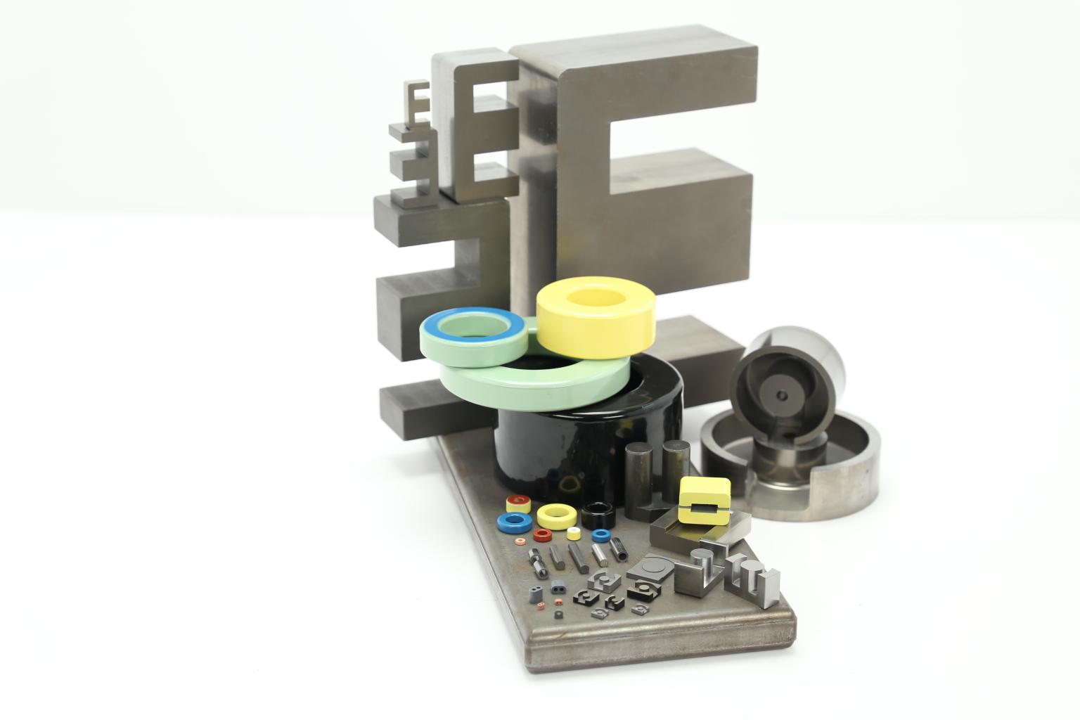
| Product Name |
Toroidal,Ring,round soft iron powder ferrite sendust(Si-Fe) Magnetic Core |
| Material |
Iron powder,sendust,alloy |
| Specification |
-52 material |
| Initial Permeability |
Ui:10-150 |
| MOQ |
1 PCS |
| Certification |
SGS-ROHS, ISO9001 |
| Payment |
T/T, Western Union, Paypal, Credit Card |
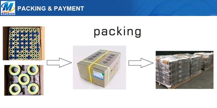
| Packing | Standard Export packageing by Pearl cotton, molded paper sheet, plastic trays,shrink wrap, or as customer's request. |
| Sample | 1~10 pcs of free samples as per detailed project |
| Application |
1. Light Choke,DC choke,power choke coil inductor. 3. Lighting and Car Electronics. 4. Computer,PDA and other electronic devices,etc- 5.Common mode choke(CMC) |




FAQ
1-MOQ?
We will work hard to fit your MOQ .Small purchase quantity is ok.
2-Payment term?
T/T, Western Union, Paypal, Credit Card
3-Delivery port?
Shenzhen, Guangzhou, Zhongshan, Hongkong.
4-Shipping date?
About 7 days when we check the payment.
5-Do you produce the core and bobbin by yourself .
Yes.we have 2 head company,1 subsidiary company.one is bobbin factory,one is core factory,last one is transformer factory.
6-Where is your factory?
In ShaanxI
Alloy Powder Core,Toroidal Iron Powder Core,Yellow White Iron Powder Core,Low Permeability Iron Powder Core
Shaanxi Magason-tech Electronics Co.,Ltd , https://www.magason-tech.com