The bidirectional current source structure used for ground loads is always more complicated. A modified Howland current pump is the most common choice for this function. It requires a carefully matched resistor or resistor network for high accuracy and performance.
The bidirectional current source structure used for ground loads is always more complicated. The improved Howland current pump shown in Figure 1 is the most common choice for this function. Howland requires a carefully matched resistor or resistor network. A precision differential amplifier can also be used, but some adjustments may still be required to achieve the desired performance.
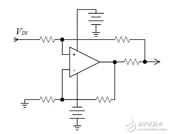
Figure 1: The classic modified Howland is used for bidirectional current output to grounded loads. This circuit requires strict component value selection and matching to achieve high accuracy and performance.
The circuit shown in Figure 2 (in this article we call it a simple current source) requires only a precision resistor to achieve the same function. As pointed out in the first paragraph, complexity is always present, and there is a need to add an isolated dual power supply that is easily available and lower in cost.
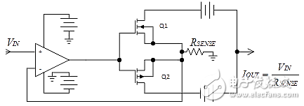
Figure 2: With a floating output stage power supply, this simple current source circuit can achieve accuracy with a single resistor. Isolated dual-output DC-DC converters come in many different power models and are easily accessible by visiting the distributor's website.
The circuit shown in Figure 2 describes an op amp that uses a simple MOSFET (or bipolar, if desired) buffer at the output. We can get feedback from the grounded resistance MOSFET source. You will find that this is similar to a classic unidirectional operational amplifier/MOSFET combination used to provide a current source. The only complication is the need to achieve power-supply floating on the MOSFET drain, while obtaining the output from the center tap of the power supply. When an op amp is used in a unity-gain configuration, gain accuracy is generally a function of the single-current sense resistor (although adding two resistors in the accuracy equation, gain can still be achieved).
In addition to the precision advantage, this circuit also has a better frequency response and inductive load because the load is not in the feedback loop, which is different from the Howland circuit. The output MOSFET unidirectional transfer function isolates the loop from the load, at least before exceeding the dynamic range. In contrast, the modified Howland requires extensive compensation using inductive loads, and the bandwidth is reduced at the same time.
Note that the simplified circuit of Figure 2 lacks the Class A/B bias of the MOSFET. For DC or low frequency applications, this may not be a problem. The actual circuit tested in Figure 3 contains a VGS multiplier configuration with one MOSFET and two resistors for A/B biasing to eliminate crossover distortion because it is also used to test transient response.
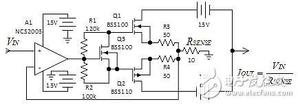
Figure 3: The actual circuit used to test the ground load current source. This circuit uses the VGS multiplier Q3 to provide the A/B bias required for high-frequency transient response testing. The 50Ω supply resistors on Q1 and Q2 eliminate MOSFET ringing during fast transitions.
The loop in Figure 3 was tested for accuracy, however Howland did not perform an accuracy check because it requires the use of 6 very stringent component values. We can say that any circuit can provide high accuracy in the end, but using the current source described in this article can greatly simplify the task.
Test Results
It may not be fair to conduct a precision test of Howland, because Howland accuracy is related to the effort that is being made. This is the problem solved by a simple current source. We can say this way, both kinds of circuit can offer high precision finally, but use simple current source can simplify the task greatly.
Accuracy testing is performed with a resistor, RSENSE, with a 0.1% accuracy. The test results are represented by an output current error graph. The goal of the test was to evaluate the performance at an output current range of +/-10mA. Figure 4 plots the output current error versus input voltage.
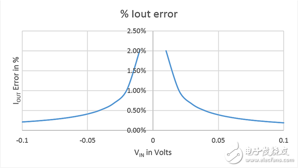
Figure 4: Output error of the circuit shown in Figure 3 (current range ±10mA).
To show the advantages of this circuit when driving inductive loads, we compare it with Howland, both driving a 50μH inductor. The schematic in Figure 5 shows how to reconfigure a simple current source as a Howland current source. In both circuits, we observe the output current with a 1Ω non-inductive resistor in series with a 50μH inductor.
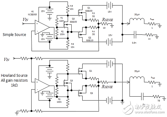
Figure 5: Test circuit to compare the dynamic response of a simple current source (top) with Howland (bottom). Observe the output signal by RTEST.
Both circuits require the use of a compensation network through the inductor for different reasons. For a simple current source, the output capacitor and load inductance need to use a buffer to control ringing. Howland also has ringing, mostly due to the inductance in the feedback loop. Using square wave input, we performed input compensation based on experience. In both circuits, we begin to use the resistance through the inductor and reduce the resistance until the overshoot and ringing are eliminated. Then, use a capacitor and lower the capacitance until the overshoot and ringing start showing the backup.
The frequency should be as high as possible, and in order to obtain a similar waveform, a frequency of 200 kHz is used. The Howland waveform in Figure 6 shows that the frequency actually exceeds Howland's limit.
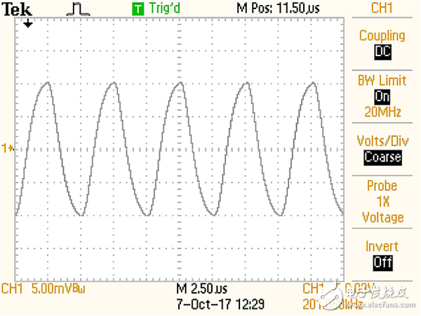
Figure 6: The Howland current source driven to ±10 mA at a 200 kHz square wave actually exceeds its frequency response limit. The amount of compensation needed to eliminate overshoot and ringing is rounded off.
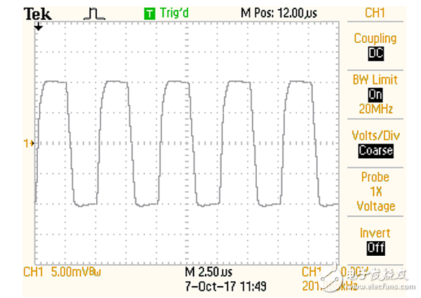
Figure 7: A simple current source shows excellent 200 kHz square wave performance because the inductive load is not part of the feedback loop. Due to the effect of output capacitance, compensation cancels ringing.
Can be simpler
If you think that Figure 2 and Figure 3 are too complex and you are willing to sacrifice some of the performance, then you can use the schematic of Figure 4 as the simplest method. At first glance, an obvious consideration is that the output pins of the op amp's power supply are used to generate the output, and its dynamic range is obviously affected by the lowest rated power supply of the op amp. When using a CMOS operational amplifier, the quiescent current flows between rails, which has little effect on the output accuracy, but a bipolar operational amplifier can exhibit several percent error. Although rail-to-rail bypass can be used, bypassing is still a problem. The author has used this circuit several times as a network analyzer's current output adapter to measure the output impedance of an operational amplifier. We have not yet tested various op amps. Although many op amps may perform well in this circuit, there are still some op amps that perform poorly.
Simulate this circuit warning. Not all operational amplifier spice models can correctly simulate the flow of load current in the power pins, which is an essential feature of the analog circuit.
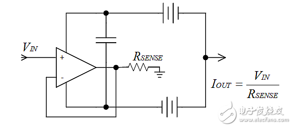
Figure 8: This is the simplest implementation of this current output circuit, but it will reduce the output impedance and limit the output specification range. In addition, you must use your choice of op amp to verify this approach, because some op amps may not be able to operate in this circuit due to power supply fluctuations.
The utility model discloses an Electronic Cigarette with atomizer oil core separation structure, which comprises a atomizer assembly and a battery assembly; The utility model has the advantages of reasonable structure design and high practicability. During operation, because the oil storage tank of the atomizer is completely sealed and the oil guide material is completely isolated from the oil guide material, the oil guide material will never contact with the oil guide material in the storage process
Advantages:
Oil core separation, Mesh removable heating core, Ultra quiet design,100% oil leakage free, Excellent taste, Cost far less than the industry price.
A variety of colors and finishing are available, can be adjusted according to your market needs.
Oil Coil Separation Pod Patent,Oil Coil Separetion Vape Pod Oem,Innovated Vape Products Oem,Oil Coil Separation Vape Products Oem
Shenzhen MASON VAP Technology Co., Ltd. , https://www.masonvap.com