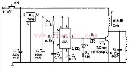
As shown in the figure, it is an automotive electronic igniter circuit composed of 555 timing circuit, voltage regulator, resistor, capacitor and so on. This circuit mainly uses the +12V power supply on the car to electronically ignite the car.
In the figure, the +12V voltage is output to 9V through the IC1 (7089) three-terminal regulator, which serves as the power supply for IC2 (555). 555 and R1, R2, C2, etc. constitute an astable multivibrator. Once it is powered up, its oscillation frequency is f=1.44/(R2+2R1)C2 The oscillation frequency of the parameter is 528Hz.
The oscillating pulse output from 555 (IC2) is applied to the base of VT1 via R3 current limit, and the step-up transformer T is driven by amplification to generate an ignition voltage of about 1500 on the ignition coil. The spark distance at high voltage discharge is up to 12 mm.

MT6-Subminiature Sealed Micro Switch
Features
â—† Designed For Water and Dust Tight(IP67)
â—† Small Compact Sizeâ—† UL&ENEC&CQC Safety Approvals
â—† Long life & high reliability
â—† Variety of Levers
â—† Wide Range of wiring Terminals
â—† Wide used in Automotive Electronics,Appliance and Industrial Control etc.
â—† Customized Designs
Safety Micro Switch,Central Locking Switch,Sealed Waterproof Micro Switch,Subminiature Sealed Micro Switch
Ningbo Jialin Electronics Co.,Ltd , https://www.donghai-switch.com