Automobile engine fuel injection technology is a matter of energy and environmental protection related to the development of internal combustion engines. With the development of electronic technology, automobile engine fuel injection systems continue to develop and become more and more perfect. The electronically controlled fuel injection system with its precise control of the fuel injection quantity makes the spray atomization good and complete combustion, which can not only improve the power of the car, but also significantly improve the power and economy of the car.
Embedded systems and single-chip microcomputers have penetrated into many technical fields. MCS-51 series single-chip microcomputers are the most widely used single-chip microcomputer series. Among them, 89V51 series single-chip microcomputers produced by Philips have the characteristics of low power consumption / low voltage and high performance. A kind of single-chip microcomputer with strong functions, high flexibility and reasonable price, especially its on-chip Flash ROM allows programming in the system or programming with a conventional non-volatile memory programmer, which brings to the development and application of single chip microcomputer convenient.
The system studied in this paper is based on an in-depth analysis of the composition and working principle of the gasoline and fuel injection electronic control system. The AT89C51 single-chip microcomputer is used as the main controller, combined with the TLC2543 serial A / D conversion chip. The peripheral circuit is designed to program the injection quantity and timing control program. The design of the hardware circuit includes the design of the sensor output signal preprocessing circuit, the design of the analog input A / D conversion circuit, and the design of the interface circuit between chips such as AT89C51 and TIC2543. The preparation of the control program mainly includes the calculation of the rotation speed, the calculation of the injection quantity and the control program of the injection timing.
1 Composition of gasoline engine fuel control system
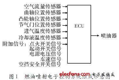
The fuel injection electronic control system is composed of various sensors and control switches, electronic control unit ECU and actuator 3 parts, as shown in Figure 1.

Automotive engine fuel injection electronic control system, the main sensors used are air flow sensor or manifold pressure sensor, crankshaft position sensor, camshaft position sensor, throttle position sensor, coolant temperature sensor, intake air temperature sensor, oxygen sensor and vehicle speed Sensors, etc .; the control switch signals collected by the electronic control unit ECU mainly include the ignition switch signal, the start switch signal, the power supply voltage signal, the air conditioner switch signal and the neutral switch signal, etc .; the actuators mainly include the electric fuel pump, the electromagnetic fuel injector and the oil pressure Regulator.
Among the control components of the fuel injection electronic control system, the air flow sensor, the crankshaft position sensor, the camshaft position sensor and the throttle position sensor are the most critical, and their signals are indispensable sensors for calculating and determining the fuel injection amount. The signals of the coolant temperature sensor, intake air temperature sensor, oxygen sensor, vehicle speed sensor and various switch signals are mainly used to judge the engine operating state, correct the fuel injection amount, and enhance the control effect.
When the engine is working, the sensors installed in different positions on the engine will send the parameters that indicate the running state of the engine to the single chip microcomputer. The single chip microcomputer analyzes and calculates according to its memory program, and then sends instructions to each actuator to make it work as required.
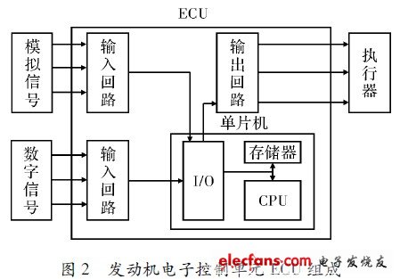
The engine electronic control unit (ECU) is mainly composed of an input circuit, a single-chip computer and an output circuit. Its structure is shown in Figure 2.

Wet Dry Vacuum Cleaner,Wet And Dry Vacuum Cleaner Price,Wet And Dry Vacuum Cleaner For Home,Wet And Dry Cordless Vacuum Cleaner
Ningbo ATAP Electric Appliance Co.,Ltd , https://www.atap-airfryer.com