1 Introduction
Profibus is an international, open field bus standard that does not depend on manufacturers, and is widely used in the field of industrial automation. Profibus is divided into three compatible versions: Profibus-DP, Profibus-FMS, and Profibus-PA according to application characteristics. Among them, Profibus-DP is a high-speed (data transmission rate of 9.6kbit / s-12Mbit / s) economical device-level network, which is mainly used for communication between field controllers and distributed I / O, which can meet AC and DC speed regulation systems. Quick response time requirements. Because of its high reliability, high performance, good real-time performance and its unique design, it has been accepted by almost all manufacturers and users.
BWS servo motor has excellent characteristics such as compact structure, easy control, smooth operation and corresponding fast, etc. It has become an important force in modern industrial automation motion control. Especially in the applications where the degree of automation is relatively high and the speed, position and torque need to be accurately controlled, such as textile machinery, printing machinery, paper machinery, CNC machine tools, industrial robots and other important industries have been widely used. Although PROFIBUS-DP is not specifically developed for motion control like SERCOS, MACRO, Fire Wire, but in the actual control because of the widespread existence of PROFIBUS-DP, the use of PROFIBUS bus to control the servo has very important practical significance.
2 PROFIBUS-DP bus technology
2.1 Introduction to PROFIBUS-DP
PROFIBUS is based on ISO7498 and uses open system interconnection network OSI (open system interconnecTIon) as a reference model to define physical transmission characteristics, bus access protocol and application functions. Its transmission rate is 9.6kbps-12Mbps, the maximum transmission distance is 100m at 12Mbps, 400m at 1.5Mbps, and it can be extended to 10km with repeaters. Up to 127 sites can be connected. PROFIBUS-DP is a high-speed and inexpensive communication connection. It uses Layer 1, Layer 2 (that is, the physical layer and the data link layer) and the user interface layer. Layers 3 to 7 are not described. The fluid structure ensures fast and effective data transmission. It is specially designed for communication between the automatic control system and the decentralized I / O of the device. Using PROFIBUS-DP module can replace 24V or 4 ~ 20mA serial signal transmission, reducing investment costs. The user interface provided by the direct data link image (DDLM) makes access to the data link layer simple and convenient. RS-485 transmission technology or fiber optic media can be used for transmission.
The hardware of the standard fieldbus PROFIBUS-DP consists of three parts: the master device, the slave device, and the network. The master device is used to control the data transmission on the bus, and sends information and is authorized to access the bus when no external request is provided. The slave device is a relatively simple external device relative to the master device, and it is not authorized to access the bus; network networks such as transmission media and network linkers, the former using shielded twisted pair cables to form the electrical network, and plastic or glass fiber optic cables Optical fiber network, or a hybrid network based on OLM conversion between two media; the latter such as RS-485 bus connector, RS-485 bus terminal, RS-485 repeater, optical link module OLM, etc.
2.2 PROFIBUS-DP communication protocol and characteristics
The PROFIBUS-DP physical layer is the same as the first layer of the ISO / OSI reference model. It uses the EIA-RS485 protocol. Depending on the data transmission rate, two transmission media, twisted pair and optical fiber, are available.

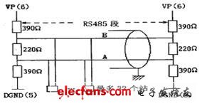
Figure 1 RS485 bus segment structure diagram
The two data lines in Figure 1 are commonly referred to as line A and line B, which correspond to the RXD / TXD-N and RXD / TXD-P signals, respectively.
The PROFIBUS-DP data link layer co-media access control (MAL) part uses controlled access token bus (Token Bus) and master-slave mode. Among them, the token bus is consistent with the IEEE8024 protocol of the local area network. The token is transmitted between the master stations on the bus. The master station holding the token obtains the bus control right. The master station communicates with the slave station or other master stations according to the relationship table. The data link protocol of the master-slave mode is different from the local area network standard, and it conforms to the unbalanced normal response mode (NRM) in HDLC. The working characteristics of this mode are: a master station on the bus controls multiple slave stations, the master station establishes a logical link with each slave station; the master station issues a command (Command), the slave station gives a response (Respond); The station can continuously send multiple frames until no information is sent, the number of sent frames is reached, or it is stopped by the master station. The frame transmission process in the data link is divided into three stages: data link establishment, frame transmission and data link release.
F in Figure 2 is the frame flag field (8 bits). A is the slave address field. The control field C indicates the frame type, number, command, and control information. It divides HDLC frames into three types: information frames (1), monitoring frames (S), and unnumbered frames (U). Among them, the information frame is used for the transmission of application data (Useful Data) and piggybacked response; the monitoring frame is used to monitor the normal operation on the link and make various responses to the link status (such as approval frame, request for retransmission or pause, etc.) ; Unnumbered frames (without information fields) are used to transmit various meta-numbered commands and responses, such as establishing link working mode, releasing links, and reporting special situations. The information field is composed of PKW + PZD application data. PKW is used to read and write parameter values, such as writing control words or reading status words, etc., which is generally 4B long, and PZD is used to store specific control values ​​of the controller and set the site Or the status word parameter is generally 2 ~ 10B long. For example, PKW = P554.1 represents writing a 16-bit control word to the main drive module of the inverter, and each bit of the control word represents a different control meaning; the second byte of PZD is 0 # ~ 7 # Motor start-stop control position. FCS is a frame check field, which performs a cyclic redundancy code (CRC) check on the contents of the entire frame, and the HDLC frame can be up to 24B in length.

Figure 2 Normal response mode Master and slave transmission frame format
3 Servo motor connected to PROFIBUS-DP network
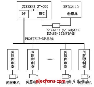
The BWS-NBBR / BBF type servo control system of Guangzhou Bowei Servo Technology Co., Ltd. provides a special PROFIBUS-DP bus interface module for its controller. It can use ordinary twisted-pair wires as a communication medium like other PROFIBUS-DP , It is very convenient to connect to the industrial control system based on PROFIBUS-DP bus, as shown in Figure 3.
The host computer is composed of Siemens S7-300PLC, the model is 6ES7315-2AG10-0AB0, it has a special PROFIBUS-DP interface, an MPI communication interface, can access 64 slave stations. The PROFIBUS-DP bus is responsible for the management of all servo controllers in the entire system, including command transmission and setting of parameters such as speed, torque, and position. As a window, the man-machine interface woven by the configuration software ProTool can conveniently monitor and modify the entire control system.
BWS-BBR / BBF uses a rotary encoder or photoelectric encoder to establish feedback between the servo controller and the servo motor to form a high-precision servo control system. The servo motor uploads its running status and information to the servo controller in real time. As a node on the PROFIBUS-DP bus, the servo controller can communicate with the PLC host and accept various operations, controls, and parameter setting commands of the host computer through the bus.

Figure 3 Schematic diagram of the servo motor connected to the PROFIBUS-DP network system
Land Rover Dash Cam,Car And Driver Dash Cam,Drive Hd Dash Cam,Landrover Dedicated Dashcam
SHENZHEN ROSOTO TECHNOLOGY CO., LTD. , https://www.rdtkdashcam.com