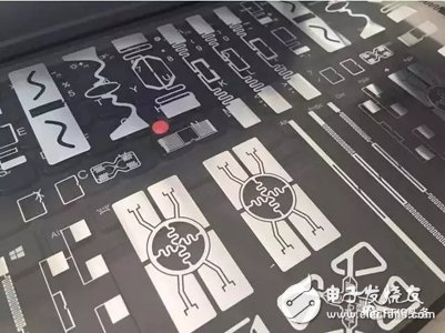
The design of the electronic tag antenna is to transmit the most energy into and out of the tag chip, which requires careful design of the antenna and free space matching, as well as the matching of the antenna and the tag chip. When the operating frequency is increased to the microwave band, the matching problem between the antenna and the electronic tag chip becomes more severe. The development of electronic tag antennas has been based on 50 or 75 input impedance. In RFID applications, the input impedance of the chip may be arbitrary, and it is difficult to accurately test under working conditions. Without accurate parameters, the antenna design is difficult. Get the best.

The design of electronic tag antennas also faces many other problems, such as corresponding small size requirements, low cost requirements, the shape and physical characteristics of the identified objects, the distance requirements of the electronic tags to the labeled objects, the dielectric constant requirements of the labeled objects, and the metal. The reflection requirements of the surface, the influence of the local structure on the radiation mode, etc., all of which will affect the characteristics of the electronic tag antenna, and are all problems faced by the electronic tag design.
RFID reader antenna designFor short-range RFID systems (such as 13.56MHz identification system less than 10cm), the antenna is generally integrated with the reader; for long-distance RFID systems (such as UHF band identification system greater than 3m), the antenna and reader often take separation Structure and connect the reader and antenna together via an impedance-matched coaxial cable. Due to the variety of structure, installation and use environment, and the development of readers' products towards miniaturization and even miniaturization, the design of reader antennas faces new challenges.
The reader antenna design requires low profile, miniaturization and multi-band coverage. For the separate readers, the design problem of the antenna array will be involved, and the low efficiency and low gain problems brought about by miniaturization will be the research topics of common concern at home and abroad. At present, the intelligent beam scanning antenna array for reader applications has been studied. The reader can use the smart antenna to perceive the electronic tag of the antenna coverage area according to a certain processing sequence, thereby increasing the system coverage and enabling the reader to It determines the orientation, velocity and direction information of the target and has spatial sensing capability.
RFID antenna design stepsThe performance of RFID tag antennas depends to a large extent on the complex impedance of the chip. The complex impedance is frequency-dependent. Therefore, the antenna size and operating frequency limit the maximum achievable gain and bandwidth. For optimal label performance, Make compromises in design to meet design requirements. In the antenna design step, the reading range of the electronic tag must be closely monitored. When the tag composition is changed or the performance of the antenna with different frequencies of different materials is optimized, the adjustable antenna design is usually adopted to meet the design tolerance.
When designing an RFID antenna, first select the type of application, determine the demand parameters of the electronic tag antenna; then determine the material used by the antenna according to the parameters of the electronic tag antenna, and determine the structure of the electronic tag antenna and the impedance after packaging; Optimized, the impedance after encapsulation is matched with the antenna, and the other parameters of the antenna are simulated to make the antenna meet the technical specifications, and the network analyzer is used to detect various indicators.
Many antennas are complicated in the use of RFID antennas because of their complicated environment. Antennas are usually analyzed using electromagnetic models and simulation tools. Typical electromagnetic model analysis methods for antennas are finite element method FEM, moment method MOM and time domain finite difference method FDTD. The simulation tool is very important for the design of the antenna. It is a fast and effective antenna design tool and is currently used more and more in the antenna technology. A typical antenna design method is to model the antenna first, then simulate the model, monitor the antenna range, antenna gain and antenna impedance in the simulation, and further adjust the design by using an optimized method. Finally, the antenna is processed and measured until it is satisfied. Claim.
Basic Features
1. The terminal has universal mounting feet so that it can be installed on U-rail NC 35 and G-rail NC32.
2. The closed screw guide hole ensures ideal screwdriver operation.
3. Equipped with uniform accessories for terminals of multiple cross-section grades, such as end plates, grouping partitions, etc.
4. Potential distribution can be achieved by inserting a fixed bridge in the center of the terminal or an edge-plug bridge inserted into the wire cavity.
5. The grounding terminal and the N-line slider breaking terminal with the same shape as the common terminal.
6. Using the identification system ZT, unified terminal identification can be realized.
7. The rich graphics enhance the three-dimensional sense of the wiring system.
Din Rail Terminal Block,Din Rail Fuse Terminal Block,Din Rail Busbar Terminal Block,Din Rail Power Terminal Blocks
Sichuan Xinlian electronic science and technology Company , https://www.sztmlch.com