The battery charger combines the high-frequency switching power supply technology and the embedded microcomputer control technology organically, and uses the intelligent dynamic adjustment technology to realize the optimized charging characteristic curve and effectively extend the service life of the battery. It adopts constant current / W phase / constant voltage / small constant current four-stage charging mode, featuring high charging efficiency, high reliability, easy operation, light weight and small size.
Battery charger main functions and features· The input AC voltage range is wide and the output DC stability is good.
· The output current is continuously adjustable.
Flexible use: It can be charged in a single unit or multiple units without the need for current sharing.
· With input and output over-current, over-voltage, under-voltage protection, and overall machine overheat protection.
·The heat dissipation adopts forced air cooling and intelligent temperature control.
·The output voltage and charging current can be flexibly adjusted according to different specifications of the battery and battery pack.
·The charging process is automatically completed in three stages of constant current and constant voltage turbulent floating charge. It will not damage the battery due to overvoltage or overcurrent.
· Digital display of voltage and current values, accurate and intuitive.
· Easy to operate and easy to use.
Battery charger main technical parameters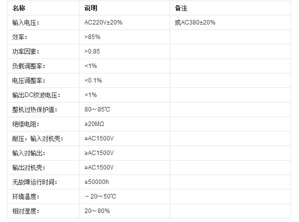
1, 1, charging voltage 2, charging current
Second, select the rated power, voltage and current of the transformer
Third, the necessary rectification, current limiting, and voltage stabilizing circuit components must reach the maximum index of the voltage and current being loaded.
For the battery, the charger was the first to use a transformer charger. However, transformer chargers are rarely used because they are too bulky, bulky, low in cost, and low in charging efficiency. Widely used is the electronic charger. The charger input AC voltage is about 220V, the output terminal is connected to the battery, and its charging mode;
First, intermittent charging and compensation are performed by charging a large current pulse; secondly, maintaining a constant charging voltage and current to the charged battery by constant current and constant voltage floating charge. The charger has output short circuit protection, output over voltage, over current protection and overshoot protection to ensure battery life.
Due to the development of fast charging technology, the concept of the fast charging performance of the traditional lead-acid battery has been changed. Experiments have shown that most VRLA batteries can withstand rapid charging, and reasonable fast charging is not only harmless but also beneficial for extending battery life.
Battery smart charger circuit (1)The circuit is shown in Figure 4-8. FU is a short-circuit protection tube, LED1 is the power supply indication, adjusting RP1 can change the output voltage of ICl, the center end of RP2 provides a reference voltage for the positive phase input terminal of voltage comparator IC2, R3 is the charging current sampling resistor, and VD can prevent the battery Discharge, LED2 is the state of charge indication, C1, C2 are used to prevent pulse interference.
The control principle of automatic stop charging is that the charging current is gradually reduced as the charging progresses, and the voltage drop on R3 is also reduced. If it is less than the set value on RP2, the relationship between the level of pin 2 of IC2 and the level of pin 3 is changed from high to low, and the output of pin 6 is changed from high level to low level, VD is reverse biased, charging The current drops to zero, at this point, because there is no voltage drop on R3. Change the 6 pin of IC2 to keep low level, LED2 light means that the battery is fully charged.
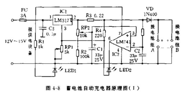
Components can be selected as shown in Figure 4-8. A heat sink should be installed on the IC1. The IC2 does not have to use the LM741. Other units of single or multiple op amps are also available.
The debugging process is as follows: first do not install IC2, do not connect the battery, adjust RPl. Make the output voltage of ICl 8.5V. Disconnect the power supply, install IC2, and connect two fully charged battery packs. Restore the power supply, adjust RP2 so that LED2 will not emit light until it starts to emit light, and fix RPl and RP2.
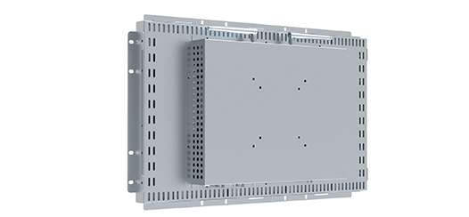
Open Frame For Resistive Touch All-in-one
Green Touch's self-developed 5A series of open frame touchscreen computers can support Windows, Linux, Android operating systems, with excellent functionality and flexibility, and provide you with reliable commercial and industrial-grade solutions. The 5A series adopts modules. Designed with diverse and powerful functions, it can be used in public environments such as in-store human-computer interaction, operating system cashiers, self-service, hotel services, and corporate offices. It has a wide range of uses, provides a variety of sizes and configuration options, and has versatility for cross-environmental use , sturdy and durable, can meet the needs of continuous public use.
* Display Type: Active Matrix TFT LCD, LED Backlight
* Touch Typeâ‘ :PCAP ,10 Points Touch
* Touch Typeâ‘¡:Infrared ,10 Points Touch
* Touch Typeâ‘¢:4 Wire Resistive/5 Wire Resistive,Single Touch
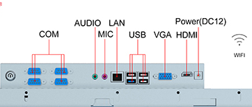
* Extra Video Output:1*VGA,1*HDMI
* Motherboard:Inter I3,I5,I7
* Supported OS:Windows,Android,Linux
* Certificates:UL,FCC,CE,CB,HDMI
* Warranty:1 Year


Open Frame Touch Computers,Open Frame Touch All In One PC,Open Frame Touch All In One Computer,Commercial All-in-one Machine
ShenZhen GreenTouch Technology Co.,Ltd , https://www.bbstouch.com