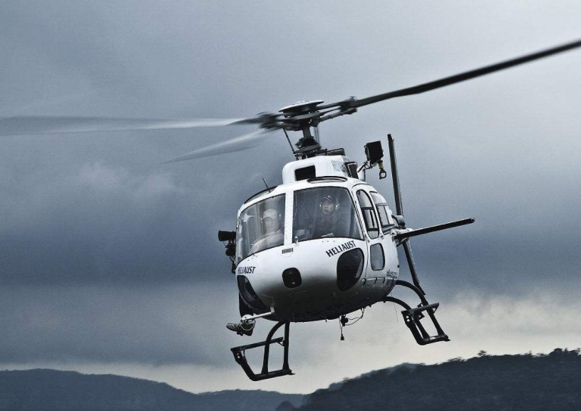
There are four forces on the helicopter in flight, which are lift, gravity, thrust and drag. Lift is the upward force generated by the movement of the rotor in the air. Gravity is opposite to the direction of lift and is generated by gravity. Thrust is the force that drives a helicopter to advance in the air. Resistance counteracts lift and thrust, which is the result of lift and the movement of the body in the air. Before you start discussing lift, you need to know some aerodynamic terms to describe the interaction of an airfoil with its surrounding airflow.
An airfoil is a surface, such as an airplane's wing or a helicopter rotor blade that produces aerodynamic forces as they move relative to the airflow. Although the rotor blade airfoil is varied, in most flight conditions, all blades work in the same way. The engineers who designed the first helicopter chose a relatively thicker airfoil due to its structural characteristics. Because the blades of the rotor are very slender, it is necessary to increase their stiffness so as to avoid excessive sagging of the rotor blades at rest and to minimize distortion of the blades during flight. The blades are also designed as symmetrical airfoils, which means that their upper and lower airfoils have the same curvature.

The symmetrical blades are very stable and help to keep the blade twisted and flight control loads to a minimum. This stability is achieved in such a way that when the angle of attack changes, the pressure center is almost constant. The pressure center is an imaginary point on a string, and all aerodynamic forces are considered to act at that point. Today, designers use composite materials to achieve the required stiffness with relatively small airfoils. In addition, the blades are not symmetrical, which means that the curvature of the upper and lower airfoils is different.
Normally, these airfoils become no longer stable, but this can be corrected by the fact that the curved trailing edge produces the same characteristics as the symmetrical airfoil. This is called "reflective." The application of such a blade can be a rotor system operating at higher forward speeds. One of the reasons for the instability of the asymmetric blade is that the pressure center changes with the change of the angle of attack. When the point of action of the lift is behind the center of rotation of the blade, the inclination of the paddle is increased.
As the angle of attack increases, the center of pressure moves forward, and if it moves to the pivot point, the pad tilt decreases. As the angle of attack of the blade changes continuously as it rotates, the blade will wave and the oscillation will become more and more serious. When referring to an airfoil, the span is the distance from the rotor of the paddle to the tip of the wing. The blade torsion angle is the angle at which the string is twisted from the root of the blade to the tip. The blade has a twist angle that causes the blade to produce greater lift. This is necessary because the linear speed of the blade is gradually increasing from the wing root to the wing tip. The wing tip is the first part that comes into contact with the incoming air. The trailing edge is where the air from the upper and lower airfoils rejoin. The string is an imaginary line connecting the wing tip to the trailing edge, and the arc is the shape of the upper and lower airfoil of the airfoil. Relative flow refers to the flow of air through the blades. The direction of the incoming flow is related to the position of the blade, and is often parallel to the flight direction of the aircraft. The angle of attack is the angle between the airfoil string and the direction of the incoming flow.
The relative flow is relative to the flow due to the movement of the blades in the air. It may be that the blades are absolutely moving, or both may have absolute motion. Relative inflows may be affected by a number of factors, including the rotation of the blades, the change in the horizontal position of the helicopter, the waving of the blades, and the wind speed and direction. For a helicopter, the relative flow refers to the flow of air through the blades. If the blades are stationary, the wind will blow through the blades to form a relative flow. If the helicopter is hovering in a windless condition, the relative flow is generated by the rotation of the blades in the air. If the helicopter hovers in the wind, the relative inflow is formed by the superposition of the motion of the wind and the blades. When the helicopter is flying forward, the relative flow is formed by the superposition of the forward speed and the rotation of the blades.
Blade pitch angle The blade pitch angle is the angle between its chord and the plane of the paddle. You use the flight control system to control the pitch of the blade, change the total pitch of the blade, and the pitch of each blade is generated. The same change, which is used to change the tension of the blade, the pitch of each blade changed by the periodic variable pitch operation depends on which position it is rotated to. This operation is used to balance the forward flight and pitch under other flight conditions. And the torque in the direction of the roll. Angle of attack When the angle of attack increases, the air flows through the airfoil to a greater extent, resulting in an increase in air velocity and lift. As the angle of attack continues to increase, the air will flow smoothly across the top of the blade. It is getting more and more difficult.
At some point the airflow begins to diverge behind the blade and enters the turbulent mode. This phenomenon greatly increases the lift and causes the lift in the turbulent region to decrease. Before reaching this point, the lift increases as the angle of attack increases. If the angle of attack exceeds this point, it will lead to stall and a sharp decrease in lift. The pitch angle cannot be confused with the concept of the angle of attack. The angle of attack depends on the direction of the relative flow, but you can also change the angle of attack by changing the pitch angle. The two increase together and decrease together. The Magnus effect of lift explains how lift is generated. You should look at the cylinder that rotates in the airflow. The local velocity of the airflow near the cylinder should be the combination of the speed of the cylinder and the velocity of the incoming flow.
On the cylinder, the rotational speed of the tip point coincides with the direction of the incoming flow, while the rotational speed of the bottom end point is opposite to the direction of the incoming flow velocity. There is an upper wash stream at the front of the cylinder and a lower wash stream at the tail. The difference in surface airflow velocity causes a difference in pressure. The pressure at the top is smaller than the pressure at the lower portion, and the low pressure region produces an upward force. This is the "Magnus effect." This explains the relationship between vortex and lift. A blade with a positive angle of attack can create a vortex because its sharp trailing edge keeps its rear stagnation point at the trailing edge and the front stagnation point below the leading edge of the airfoil.
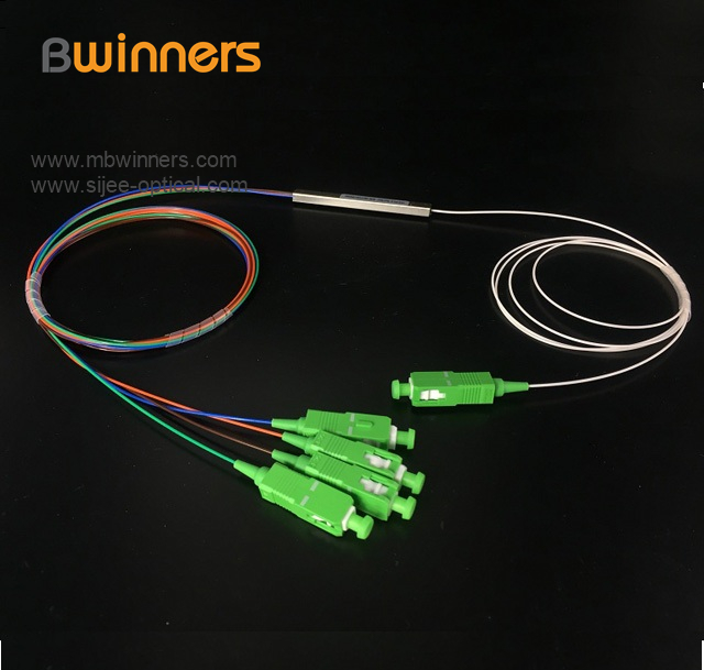
Fiber optic splitter is also called optical splitter, is one of the most important passive devices in optical fiber link, is with multiple inputs and multiple output end of the optical fiber connected devices. The fiber optic splitter by the light splitting principle can be divided into the fused biconical taper (FBT type) and planar waveguide type (PLC type).
We provide the whole series of 1xN and 2xN splitter products that are tailored for specific applications. Fiber Optic Splitter Plc, Fiber Optic Cable Splitter, Optical Splitter, Mini Type Plc Splitter, Cassette Type PLC Splitter, Insertion Module Plc are available.


Steel Tube PLC Splitter,Plc Splitter Steel Tube,Tube Type Fiber Optic Splitter,Fiber Optic Plc
Sijee Optical Communication Technology Co.,Ltd , https://www.sijee-optical.com